Siemens Industry, Inc.
Building Technologies Division
P/N 315-050537-3
22
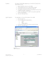
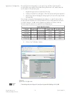
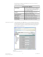
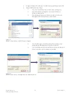
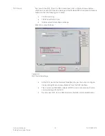
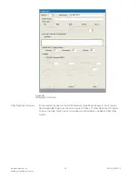
The following table describes the possible entries in the System Save & Load via
HTTP feature.
P
T
T
H
A
I
V
D
A
O
L
&
E
V
A
S
M
E
T
S
Y
S
e
l
i
f
n
o
i
t
a
r
u
g
i
f
n
o
C
e
h
t
f
o
h
t
a
p
r
e
d
l
o
f
o
s
l
a
y
l
b
i
s
s
o
p
d
n
a
e
m
a
N
t
a
h
t
)
s
r
e
t
c
a
r
a
h
c
2
3
m
u
m
i
x
a
m
(
e
l
i
f
n
o
i
t
a
r
u
g
i
f
n
o
c
h
c
t
i
w
s
r
e
b
i
f
e
c
n
a
l
a
c
S
e
h
t
n
o
d
a
o
l
o
t
t
n
a
w
u
o
y
t
n
e
r
r
u
c
e
h
t
e
r
o
t
s
o
t
t
n
a
w
u
o
y
e
r
e
h
w
r
o
.
n
o
i
t
a
m
r
o
f
n
i
n
o
i
t
a
r
u
g
i
f
n
o
c
e
l
i
F
g
o
L
t
n
e
v
E
y
l
n
o
t
n
a
v
e
l
e
r
(
)
s
e
h
c
t
i
w
s
T
R
I
r
o
f
t
n
e
v
e
e
h
t
e
v
a
s
n
a
c
u
o
y
"
,
e
v
a
S
"
g
n
i
k
c
il
c
y
B
.
C
P
r
u
o
y
o
t
)
e
l
i
f
g
o
l
t
n
e
v
e
(
e
l
b
a
t
e
l
i
F
e
r
a
w
m
r
i
F
e
h
t
d
a
o
l
o
t
h
s
i
w
u
o
y
h
c
i
h
w
m
o
r
f
e
m
a
n
h
t
a
p
ll
u
F
.
e
r
a
w
m
r
i
f
w
e
n
DIAGNOSTICS
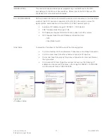
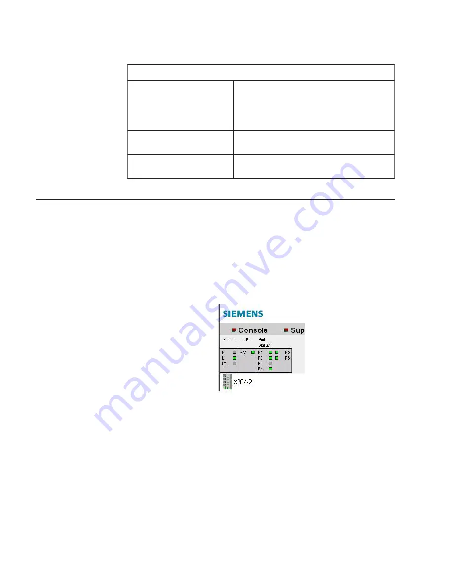
Diagnostics of the fiber switch can be done remotely, as explained below:
•
Launch web browser and type in URL of the fiber switch on which diagnos-
tics will be run
•
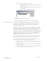
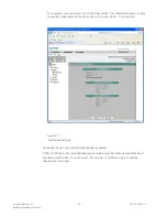
The LEDs status on the top left of the screen are the exact same as that
shown on the fiber switches.
Red indicates an error.
Green LEDs indicate that the switch is running properly.
Green also indicates ports that have an Ethernet connection to them.
Figure 29
Fiber Switch Diagnostic Indicators

