Document Number 129-409
RWD45U Controller Installation and Commissioning Guide
October 5, 2009
Page
6 of 13
Siemens Industry, Inc.
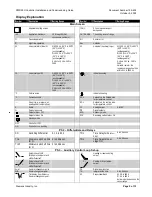
Display Explanation, Continued
Symbol
Description
Setting Range
Symbol
Description
Setting Range
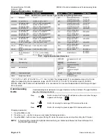
PS 2 – Unit X1, X2 and X3 Sensor Type and Sensing Range Definition
Unit
Define unit
°F or °C
ΔX1
Calibration offset for X1
(Ni and Pt sensor only)
-9°F to 9°F
-5 K to 5 K or
X1NI 1000 X1 is Ni 1000
Ω
temperature sensor
Ni 1000
Ω
: -58°F to 302°F
(-50°C to 150°C) (unchangeable)
ΔX2
Calibration offset for X2
(Ni and Pt sensor only)
-9°F to 9°F
-5 K to 5 K or
X2NI 1000 X2 is Ni 1000
Ω
temperature sensor
Ni 1000
Ω
: -58°F to 302°F
(-50°C to 150°C) (unchangeable)
ΔX3
Calibration offset for X3
(Ni and Pt sensor only)
-9°F to 9°F
-5 K to 5 K or
X3NI 1000 X3 is Ni 1000
Ω
temperature sensor
Ni 1000
Ω
: -58°F to 302°F
(-50°C to 150°C) (unchangeable)
X1L
Start point of the X1
(for 0 to 10 Vdc only)
-100 to 2400
X1Pt 1000 X1 is Pt 1000
Ω
temperature sensor
Pt 1000
Ω
: -4°F to 356°F
(-20°C to 180°C) (unchangeable)
X2L
Start point of the X2
(for 0 to 10 Vdc only)
-100 to 2400
X2Pt 1000 X2 is Pt 1000
Ω
temperature sensor
Pt 1000
Ω
: -4°F to 356°F
(-20°C to 180°C) (unchangeable)
X3L
Start point of the X3
(for 0 to 10 Vdc only)
-100 to 2400
X3Pt 1000 X3 is Pt 1000
Ω
temperature sensor
Pt 1000
Ω
: -4°F to 356°F
(-20°C to 180°C) (unchangeable)
X1H
Stop point of the X1
(for 0 to 10 Vdc only)
-100 to 2400
X1 0-10
X1 is 0 to 10 Vdc input
sensor
0 to 10 Vdc: -100 to 2400
X2H
Stop point of the X2
(for 0 to 10 Vdc only)
-100 to 2400
X2 0-10
X2 is 0 to 10 Vdc input
sensor
0 to 10 Vdc: -100 to 2400
X3H
Stop point of the X3
(for 0 to 10 Vdc only)
-100 to 2400
X3 0-10
X3 is 0 to 10 Vdc input
sensor
0 to 10 Vdc: -100 to 2400
X2SP
Remote setpoint
0 to 10 Vdc or
0 to 1000
Ω
X3
If X3 is independent
control
°C, °F, % ----(no unit display),
X1: 0 to 50°C
⇒
Y1: 0 to 10 Vdc **
X2VR
Variable Resistor
0 to 1000
Ω
PS 1 – Application Number Selection:
Standby mode
AVERAGE
Averaging sensor X1 and
X2
REM
Remote setting
WIN/SUM
AnG
Winter/Summer
changeover by analog
input
ALARM
Alarm indication
WIN/SUM
diG
Winter/Summer
changeover by digital
input
FILTER
Filter alarm indication
X2
⇔
X1
Selecting X2 or X1 as the
main sensor
COMP
Setpoint reset function
Act
Active sensor input
** (X1: 32°F to 122°F (0°C to 50°C)
⇒
Y1: 0 to 10 Vdc). The independent Y1 is programmed as a 0 to 10 Vdc
output corresponding to a temperature range of 32°F to 122°F (0°C to 50°C) for sensor input X1 (Ni1000,
Pt1000). When this function is selected there is no economizer or a second independent control loop, and input
X3 is not used.
Commissioning
Guide
Commissioning is implemented via push buttons on the controller. The push buttons
have the following functions:
Press
Button to enter the PS page OR edit and save the value when the page
appears with the logo
Press
+
Button for viewing the next page OR to increase the value.
Press
Button for viewing the previous page OR to decrease the value.
Changing a parameter
1. Press the
SEL
λ
button.
:
2. Press the
+
σ
or
–
τ
button to increase or decrease the flashing parameter.
3. Press the
SEL
λ
button to save the value (During PS mode, the values are saved only after exiting the PS mode).
NOTE:
A 9-pin port is provided for optional commissioning via Siemens software tool. See
Software Tool
(Optional Programming).
SEL
+

