Chapter 2
Installing the Device
RUGGEDCOM RST2228
Installation Guide
10
Mounting the Device to a Panel
2. Insert the device into the rack. To make the modules and ports accessible from the front, insert the power
supply side of the device first. Reverse the orientation to have the power supplies, management ports and
LEDs accessible from the front.
NOTE
Since heat within the device is channeled to the enclosure, it is recommended that 1 rack-unit
of space, or 44 mm (1.75 in), be kept empty above the device. This allows a small amount of
convectional airflow.
Forced airflow is not required. However, any increase in airflow will result in a reduction of
ambient temperature and improve the long-term reliability of all equipment mounted in the rack
space.
3. Secure the adapters to the rack using M6 or #10-32 screws.
Section 2.3.2
Mounting the Device to a Panel
For panel installations, the RUGGEDCOM RST2228 can be ordered with panel adapters for each side of the chassis.
The adapters allow the device to be attached to a panel using screws.
To mount the device to a panel, do the following:
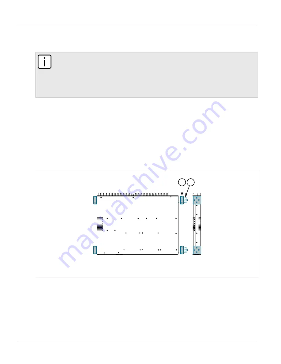
1. Secure the mounting adapters to both sides of the chassis.
1
2
Figure 5: Installing the Mounting Adapters
1.
Mounting Adapter
2.
Screw
2. Place the device against the panel and align the adapters with the mounting holes.
Содержание RUGGEDCOM RST2228
Страница 30: ...Chapter 3 Device Management RUGGEDCOM RST2228 Installation Guide 24 Inserting Removing the CLP ...
Страница 36: ...Chapter 4 Communication Ports RUGGEDCOM RST2228 Installation Guide 30 Installing Removing Modules ...
Страница 42: ...Chapter 5 Technical Specifications RUGGEDCOM RST2228 Installation Guide 36 Dimension Drawings ...
Страница 50: ...Chapter 6 Certification RUGGEDCOM RST2228 Installation Guide 44 EMC and Environmental Type Tests ...


