background image


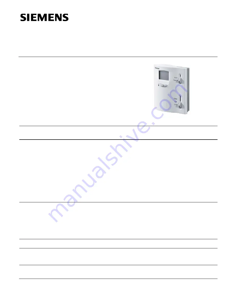
RDX42.22U 

Technical Instructions 

Document No. 155-747


March 13, 2008 


Room Temperature Controller 
with LCD 


Siemens Industry, Inc. 

Description 

Controller for heat pump systems with reversing valve, optional electric heater, one- or 
two-stage heating and one-stage cooling. 

Features 

  Outputs for one-stage compressor and reversing valve or on/off valve actuators 

  Output for auxiliary electric heating 

  Output for a one-speed fan  

  Room or return air temperature control 

  Manual heating/cooling changeover 

  Operating modes: Normal (heating, cooling), Energy Saving, Off 

  Operating mode changeover input for remote control 

  Selectable installation and control parameters 

  Operating voltage 24 Vac 

Application 

  For control of heat pump systems with reversing valve, optional electric heater, one- 

or two-stage heating and one-stage cooling 

  For control of room temperature in individual rooms that are heated or cooled with 

four-pipe fan coil units and optional electric heating 

  For opening and closing a valve 

  For switching a one-speed fan 

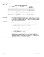
Product Number 

RDX42.22U 

Accessories 

ARG70 

Adapter Plate for 4 × 4-inch conduit boxes 

QAH11.1 

Changeover/Remote Temperature Sensor 

141-570 

Lockable Thermostat Guard 

Ordering 

The QAH11.1 temperature sensor (can also be used as a return air temperature 
sensor) and the zone valves must be ordered separately. 

Содержание RDX42.22U

Страница 1: ...ng mode changeover input for remote control Selectable installation and control parameters Operating voltage 24 Vac Application For control of heat pump systems with reversing valve optional electric heater one or two stage heating and one stage cooling For control of room temperature in individual rooms that are heated or cooled with four pipe fan coil units and optional electric heating For open...

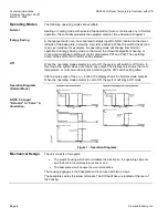
Страница 2: ...table Fan Operation Fan operation is selected on the controller s front panel either in Auto or Fan On mode When function Auto temperature dependent is selected the fan is switched on off one speed depending on the temperature and the control output When function Fan On is selected the fan will run continuously one speed The fan is switched off by leaving the heating or cooling sequence if the Tem...

Страница 3: ...ute adjustable see Parameters The auxiliary heating equipment receives the off command via control output terminal 7 when 1 The measured room temperature is above the setpoint differential between heating and auxiliary heating WD adjustable with parameters P12 and 2 The auxiliary heating output has been on for more than one minute adjustable see Parameters Cooling Mode On When the operating mode s...

Страница 4: ...02 The operating action of the switch NC or NO can be selected Off When the operating mode selector is set to Off the system will switch to Off mode In this mode the system does not activate any output The display only shows the room temperature or normal mode setpoint according to the DIP switch setting table After a single press of the or button the display shows the Normal mode setpoint When th...

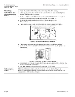
Страница 5: ...s for adjusting the setpoints and setting the control parameters 9 Operating mode selector Heat Off Cool 10 Fan control Auto Controller switches fan on when heating or cooling output is active Fan On Fan is constantly running Table 2 DIP Switch Table DIP Switch Function Position OFF Position ON 1 Operating action of remote ON OFF switch Changeover activated when switch is open NC Changeover activa...

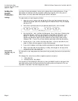
Страница 6: ...y pressing the and buttons To exit from the individual parameter setting mode press the and buttons simultaneously again and the parameter mode setting number will be displayed Pxx You can now choose another parameter mode number setting 4 By pressing the and buttons simultaneously again or five seconds after the last press of a button the last parameter will be displayed again 5 If you wish to di...

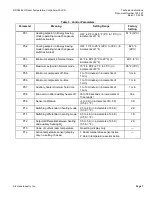
Страница 7: ...F 35 C P05 Minimum compressor off time 1 to 10 minutes in increments of 1 min 3 min P06 Minimum compressor on time 1 to 10 minutes in increments of 1 min 1 min P07 Auxiliary heater minimum hold time 1 to 10 minutes in increments of 1 min 1 min P08 Fan overrun after auxiliary heater off 30 to 300 seconds in increments of 10 seconds 30 s P09 Sensor calibration 3 to 3 K in increments of 0 5 K 0 5 K F...

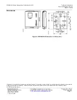
Страница 8: ...ve the floor See Figure 3 The connecting wires can be run to the controller from a recessed conduit box Figure 3 Acceptable Mounting Locations The cables used must satisfy the insulation requirements for 24 Vac potential To access the wire terminal block loosen the cover screw and open the plastic cover See Figure 4 Figure 4 Accessing the Wire Terminal Block Sensor inputs 9 8 carry 24 Vac potentia...

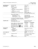
Страница 9: ...ible cable length with copper cable 262 ft 80 m 2 16 AWG or 1 14 AWG for connection to terminals 8 and D1 Operational data Setpoint setting range 46 F to 95 F 8 C to 35 C Control deviation at 77 F 25 C Maximum 1 F 0 5 K Setting Range Factory Setting Switching differential in heating mode adj 1 F to 7 F 3 5 F 2 K Switching differential in cooling mode adj 1 F to 7 F 2 F 1 K Setpoint differential WD...

Страница 10: ...0 Heating output NO contact 11 Heating output NC contact 12 Fan output at single speed D1 GND Signal input for potential free operating mode changeover Wiring Diagrams Figure 6 Four pipe System Wiring Figure 7 Heat Pump Wiring 6 Cooling output NC contact 5 Cooling output NO contact 11 Heating output NC contact 10 Heating output NO contact 6 Cooling output NC contact for reversing valve 5 Cooling o...

Страница 11: ...e introduced Product or company names mentioned herein may be the trademarks of their respective owners 2008 Siemens Industry Inc Siemens Industry Inc Building Technologies Division 1000 Deerfield Parkway Buffalo Grove IL 60089 1 847 215 1000 Your feedback is important to us If you have comments about this document please send them to SBT_technical editor us sbt siemens com Document No 155 747 Pri...

Отзывы: