Technical Instructions
RDX42.22U Room Temperature Controller with LCD
Document Number 155-747
March 13, 2008
Page 4
Siemens Industry, Inc.
Operating Modes
Normal
The following operating modes are available:
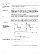
Heating or cooling mode with selected fan operation (Auto or continuous on). In Normal
operation, the controller maintains the adjusted setpoint. (See
Operation Diagram
).
Energy Saving
A changeover switch can be connected to status input D1-GND, located on the lower
left side of the base plate, below the main terminal block. When the switch closes (due
to an open window, for example), the operating mode will change from Normal
operation to Energy Saving mode. In that case, the relevant setpoints of heating or
cooling are maintained (setting of control parameters P01 and P02). The operating
action of the switch (NC or NO) can be selected.
Off
When the operating mode selector is set to Off, the system will switch to Off mode. In
this mode, the system does not activate any output. The display only shows the room
temperature, or normal mode setpoint, according to the DIP switch setting table.
After a single press of the
+
or
–
button, the display shows the Normal mode setpoint.
When the operating mode selector is set to Off, the system will stay in Off mode.
Operation Diagrams
(Normal Mode)
NOTE: Changed
"Actuator" to "Valve" in
illustration.
Figure 1. Operation Diagrams.
Mechanical Design
The unit consists of two parts:
•
The plastic housing which accommodates the electronics, the operating elements
and the built-in room temperature sensor, and
•
The baseplate, which houses the wire terminations.
The housing engages in the baseplate and is secured with two screws.
The baseplate carries the screw terminals. The DIP switches are located at the rear of
the housing.


