background image

5

Figure 3

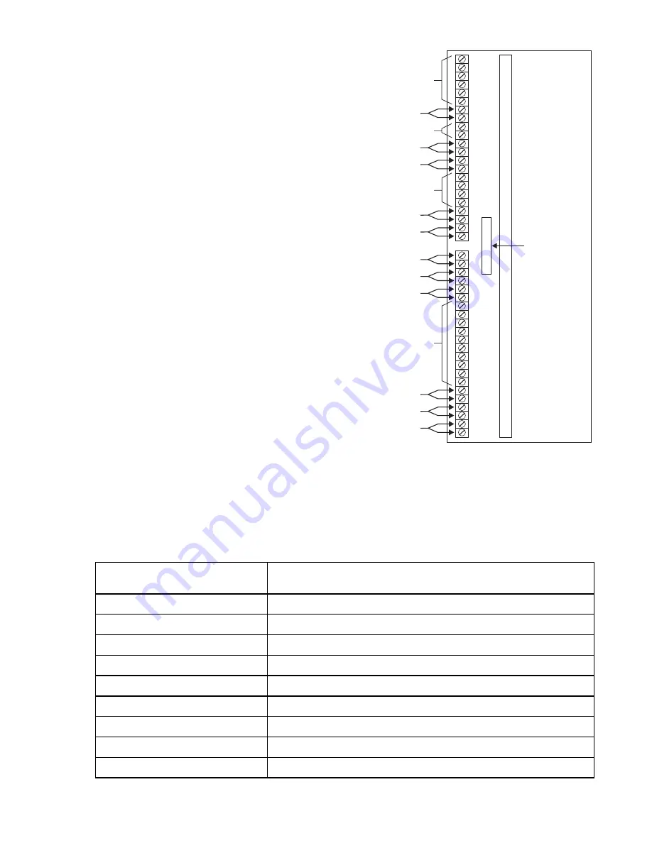
Description of the RCM-1 Terminals

The RCM-1 can be connected in many different ways. Table 2 describes the various applications. The
block diagrams below show the possible configurations.

Note:

Polarity must be observed
with all riser connections.
Odd pins are

 hi

 side while

even pins are

 lo

 side. See

the separate wiring
connections for the ACM/
TBM and the OCC shown
in Figure 12.

TABLE 2

RCM-1 APPLICATIONS

Application No.

(See Corresponding Diagram)

Configuration

1

Typical Style 4 installation

2

Style 4 installation with a Style 4 output only extension

3

Typical Style 7 installation

4

Style 7 installation with a Style 4 extension

5

Style 4 installation with fiber optic transmission

6

Style 4 fiber optic with a Style 4 fiber optic output only extension

7

Style 7 fiber connections with a Style 4 output only fiber extension

8

Combination wire and fiber installation

9

Style 4 Repeater Installation

1
2
3
4
5
6
7
8
9

10

11

12
13
14
15
16
17
18
19
20
21
22

1
2
3
4
5
6
7
8
9

10

11

12
13
14
15
16
17
18
19
20
21
22

PORT C: Copper Interface, Transmit, Style 4 (CT4)

PORT B: Copper Interface, Receive, Style 4 (BR4)

PORT B: Copper Interface, Transmit, Style 4 (BT4)

PORT B: Copper Interface, Receive, Style 7 (BR7)

PORT B: Copper Interface, Transmit, Style 7 (BT7)

NOT USED

NOT USED

NOT USED

NOT USED

PORT B: Fiber Interface, Style 4 (BF4)

PORT B: Fiber Interface, Style 7 (BF7)

PORT C: Fiber Interface, Style 4 (CF4)

CABLE TO
MMB OR PSR
P/N 555-190967

PORT D: Copper Connection To The OCC

PORT D: Copper Connection To The OCC

PORT A: Copper Connection To The ACM

RCM-1

OMM-1

or

OMM-2

Содержание RCM-1

Страница 1: ...lation Instructions Model RCM 1 Riser Control Module Fire Safety Siemens Building Technologies Inc 8 Fernwood Road Florham Park New Jersey 07932 Siemens Building Technologies Ltd 2 Kenview Boulevard Brampton Ontario L6T 5E4 CN ...

Страница 2: ... C Fiber Optic Extension 8 Application 8 Combination Wire and Fiber Installation 9 Application 9 Style 4 Repeater Installation 9 INSTALLATION 9 Network Address Programming S1 Table 3 10 S2 Settings Table 4 11 Application 1 Typical Style 4 Connections 12 Application 2 Typical Style 4 Connections with PORT C Extension 13 Application 3 Typical Style 7 Connections 14 Application 4 Style 7 Connections ...

Страница 3: ...fer to Figure 2 for their location PORT STYLE FUNCTION A 6 Audio signal input B 4 7 Audio signal input output C 4 Audio signal output D 6 Audio signal output The RCM 1 supervises Port B for open and short circuits reports by exception to the MXL and isolates the fault INTRODUCTION The Model RCM 1 Riser Control module from Siemens Building Technologies Inc provides control and supervision of global...

Страница 4: ...en Lights when the RCM 1 transmits voice using the copper wire XMIT connections XMIT F Green Lights when the RCM 1 transmits voice using any of the fiber optic ports LM1 Green Lights when the RCM 1 is in local mode Flashes when there is no valid carrier on the riser GM1 Green Lights when the RCM 1 is in global mode 1 Flashes when there is no valid carrier on the riser GM2 Green Lights when the RCM...

Страница 5: ...ptic transmission 6 Style 4 fiber optic with a Style 4 fiber optic output only extension 7 Style 7 fiber connections with a Style 4 output only fiber extension 8 Combination wire and fiber installation 9 Style 4 Repeater Installation 1 2 3 4 5 6 7 8 9 10 11 12 13 14 15 16 17 18 19 20 21 22 1 2 3 4 5 6 7 8 9 10 11 12 13 14 15 16 17 18 19 20 21 22 PORT C Copper Interface Transmit Style 4 CT4 PORT B ...

Страница 6: ...ical Style 4 Installation Application 3 Typical Style 7 Installation Application 2 Style 4 with a Style 4 Output Only Extension RCM 1 Nos 4 5 and 6 have local ACMs but cannot output to the global bus they can only receive ...

Страница 7: ...7 Application 4 Style 7 with a PORT C Extension Application 5 Style 4 Fiber Optic Installation ...

Страница 8: ...8 Application 6 Style 4 Fiber Optic with a PORT C Fiber Optic Extension Application 7 Style 7 Fiber Optic with a PORT C Fiber Optic Extension ...

Страница 9: ...1 to set the MXL network address Set this switch according to the address where the RCM 1 is installed in the MXL s network map Refer to the AccuLINK CSG M configuration printout for the address of the module See Table 3 for settings In addition to S1 which is used to set the network address the RCM 1 has a second bank of dipswitches S2 which must be correctly config ured for the RCM 1 to operate ...

Страница 10: ...O X X X O X X X O X X X O O O O X X X X O X O O X X X X O O X O X X X X O X X O X X X X O O O X X X X X O X O X X X X X O O X X X X X X O X X X X X X X O 8 2 1 9 2 1 0 3 1 1 3 1 2 3 1 3 3 1 4 3 1 5 3 1 6 3 1 7 3 1 8 3 1 9 3 1 0 4 1 1 4 1 2 4 1 3 4 1 4 4 1 5 4 1 6 4 1 7 4 1 8 4 1 9 4 1 0 5 1 1 5 1 2 5 1 3 5 1 4 5 1 5 5 1 6 5 1 7 5 1 8 5 1 9 5 1 0 6 1 1 6 1 2 6 1 3 6 1 4 6 1 5 6 1 6 6 1 7 6 1 8 6 1 ...

Страница 11: ...nection 1 0 Spare 0 0 Spare 7 Style On for Style 4 Off for Style 7 NOTE To open a dipswitch press down on the side of the dipswitch marked OPEN To close a dipswitch press down on the side of the dipswitch opposite the side marked OPEN To open a slide switch push the slide to the side opposite the side marked ON To close a slide switch push the slide to the side marked ON Use switch S2 to set the c...

Страница 12: ...UTION INSERT THE RCM 1 MODULE IN THE OMM 1 2 WITH THE ELECTRONIC COMPONENTS FACING OUTWARD TOWARDSTHEOMMSCREWTERMINALS INSTALLATION IN ANY OTHER WAY WILL CAUSE DAMAGE TO THE RCM 1 Typical Style 4 Connections Application 1 See Figure 4 This is the basic configuration of the RCM 1 It allows multiple networked MXL voice systems to be connected together to act as one large integrated voice evacuation ...

Страница 13: ... supported Notes 1 Use 18AWG minimum wire 2 Limit the maximum resistance of loop total from the first RCM to the last RCM to 100 ohms Maximum line capacitance 1µF 3 The wiring is power limited to NFPA 70 per NEC 760 4 Maximum voltage is 1 5V RMS 5 Maximum current is 50mA 6 Refer to Figure 12 for proper EOLR placement 7 Refer to Wiring Specification for MXL MXL IQ and MXLV Systems P N 315 092772 re...

Страница 14: ... line capacitance 1µF 3 The wiring is power limited to NFPA 70 per NEC 760 4 Maximum voltage is 1 5V RMS 5 Maximum current is 50mA 6 Refer to Figure 12 for proper EOLR placement 7 Refer to Wiring Specification for MXL MXL IQ and MXLV Systems P N 315 092772 revision 6 or higher for additional wiring information 8 Positive and negative ground fault detected at 50K ohms for terminals 17 20 Typical St...

Страница 15: ... 13 14 15 16 17 18 19 20 21 22 NOT USED CABLE TO MMB OR PSR P N 555 190967 RCM 1 OMM 1 or OMM 2 NOT USED NOT USED NOT USED Notes 1 Use 18AWG minimum wire 2 Limit the maximum resistance of loop total from the first RCM to the last RCM to 100 ohms Maximum line capacitance 1µF 3 The wiring is power limited to NFPA 70 per NEC 760 4 Maximum voltage is 1 5V RMS 5 Maximum current is 50mA 6 Refer to Figur...

Страница 16: ...60 4 Maximum voltage is 1 5V RMS 5 Maximum current is 50mA 6 Refer to Figure 12 for proper EOLR placement 7 Refer to Wiring Specification for MXL MXL IQ and MXLV Systems P N 315 092772 revision 6 or higher for additional wiring information 8 Positive and negative ground fault detected at 50K ohms for terminals 1 6 and 17 20 Typical Style 4 Fiber Optic Connections with Optional PORT C Extension App...

Страница 17: ...PA 70 per NEC 760 4 Maximum voltage is 1 5V RMS 5 Maximum current is 50mA 6 Refer to Figure 12 for proper EOLR placement 7 Refer to Wiring Specification for MXL MXL IQ and MXLV Systems P N 315 092772 revision 6 or higher for additional wiring information 8 Positive and negative ground fault detected at 50K ohms for terminals 1 6 and 17 20 Typical Style 7 Fiber Optic Connections with Optional PORT ...

Страница 18: ...1 or OMM 2 NOT USED NOT USED Notes 1 Use 18AWG minimum wire 2 Limit the maximum resistance of loop total from the first RCM to the last RCM to 100 ohms Maximum line capacitance 1µF 3 The wiring is power limited to NFPA 70 per NEC 760 4 Maximum voltage is 1 5V RMS 5 Maximum current is 50mA 6 Refer to Figure 12 for proper EOLR placement 7 Refer to Wiring Specification for MXL MXL IQ and MXLV Systems...

Страница 19: ...m wire 2 Limit the maximum resistance of loop total from the first RCM to the last RCM to 100 ohms Maximum line capacitance 1µF 3 The wiring is power limited to NFPA 70 per NEC 760 4 Maximum voltage is 1 5V RMS 5 Maximum current is 50mA 6 Refer to Figure 12 for proper EOLR placement 7 Refer to Wiring Specification for MXL MXL IQ and MXLV Systems P N 315 092772 revision 6 or higher for additional w...

Страница 20: ...Style 4 connections to the OCC Figure 12 Wiring Configurations for the OCC and ACM P N 315 093878 11 RCM Style 6 connections to the OCC RCM Style 4 connections to the ACM RCM Style 6 connections to the ACM ...

Отзывы: