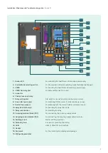
1: Amber LED
- For indicating the healthiness of incoming power supply
2: Starter Mode selecting switch
- For the selection of starter operating mode (Auto,Manual, Bypass)
3: LMRA
- For checking the healthiness of incoming power supply
4: LMRA On delay dial
- On delay setting dial (0.5-5min)
5: Contactor
6: Thermal overload relay
7: Relay setting dial
- Dial which can be set according to the motor current
8: Green NO Aux.contact
- For switching ON the motor if starter enclosure is open
9: Red NC Aux.contact
- For switching OFF the motor if starter enclosure is open
10: Relay Red test button
- For checking the relay trip circuit
11: Relay reset button
- For resetting the relay
12: Incoming terminal block (TB1)
- For connecting the incoming supply cables
13: Outgoing terminal block (TB2)
- For connecting the outgoing supply cables to motor
14: Earthing screw
- Starter earthing provision
15: Mounting hole
- 4x holes for mounting the starter
16: Links
- Links of ON & OFF push buttons
17: Gasket
18: Grommet
- For the incoming & outgoing cable passage
19: Wiring diagram label
1
2
3
4
7
9
11
13
15
17
19
5
6
8
10
12
14
16
18
4
Installation, Maintenance & Troubleshooting guide
| Version 01
Содержание RAJA+ 3TE7111-2BC21-1A Series
Страница 1: ...Installation Maintenance Troubleshooting Guide For RAJA Agriculture Starters Controllers ...
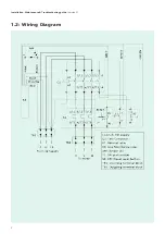
Страница 5: ...1 2 Wiring Diagram Installation Maintenance Troubleshooting guide Version 01 5 ...
Страница 6: ...6 Control logic diagram Installation Maintenance Troubleshooting guide Version 01 ...
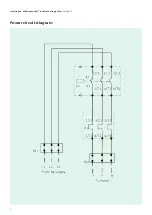
Страница 7: ...7 Power circuit diagram Installation Maintenance Troubleshooting guide Version 01 ...


