background image

120 / 176

Siemens

Web server OZW772... V6.0

CE1C5701en

Building Technologies

Trend functions

2015-10-12

The following information is displayed for a maximum of 5 trends:

·

 Name

·

 Status

·

  Query interval

·

  Circular logging (length of the history window)

·

  Bus load per trend

The sum of the bus load for all active trends is displayed below the table using the
"Bus load" bar.

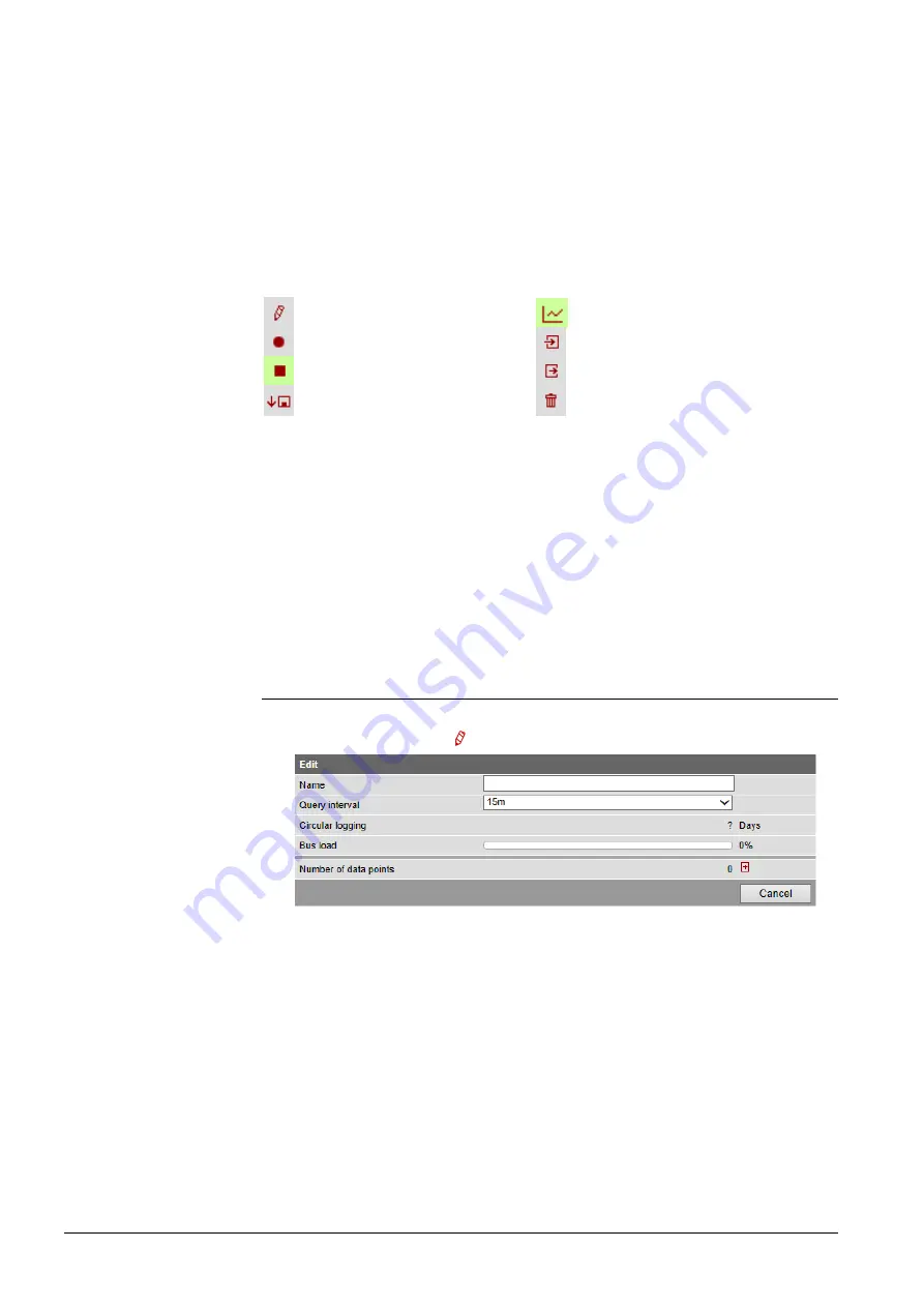
The red symbols in the trend overview are buttons with the following functions:

Create or edit trend

Generate trend graph

Start trend recording

Import trend definitions

Stop trend recording

Export trend definitions

Download trend data

Delete trend data and trend
definitions

A trend channel can have the following states:

Invalid

: Trend is state

invalid

 as long as no data points are defined in trend, e.g. in

delivery state or after deleting a trend definition.

Process completed

: The trend is in state "Process completed" as soon as data

points are defined that the trend is stopped or not yet started".

Running

: The trend is in state "In progress" if trend recording is started.

9.2  Define 

trend

9.2.1  Define trend via web

You define trends on the trend overview page.

1.  Click the red pencil  to create or edit a trend. The

Edit

 window opens.

2.  Enter trend name.

Trend information

Buttons

Trend states

Содержание OZW772 Series

Страница 1: ...s Synco Synco living Web server OZW772 V6 0 Commissioning instructions OZW772 01 OZW772 04 OZW772 16 OZW772 250 CE1C5701en 2015 10 12 Building Technologies ...

Страница 2: ...lding Technologies 2015 10 12 Siemens Switzerland Ltd Building Technologies Division International Headquarters Gubelstrasse 22 6301 Zug Switzerland Tel 41 41 724 24 24 www siemens com buildingtechnologies Siemens Switzerland Ltd 2009 Subject to change ...

Страница 3: ... 5 2 Operating page Faults current 24 2 5 3 Operating page Settings 24 2 5 3 1 Web Server 24 2 5 3 2 Time of day date 24 2 5 3 3 Communication 25 2 5 3 4 Message receivers 28 2 5 3 5 System report 31 2 5 3 6 Consumption data 32 2 5 3 7 Energy indicator 33 2 5 3 8 Trend 34 2 5 3 9 Faults 34 2 5 3 10 Texts 35 2 5 4 Operating page Device information 35 2 6 Commission network components 36 2 6 1 Acces...

Страница 4: ...nergy indicator function 80 7 1 Introduction 80 7 1 1 Function description 80 7 1 2 KNX bus topology 81 7 1 3 Synco product range 82 7 1 4 Navigation and device web pages 83 7 2 Energy indicator function levels 84 7 2 1 Plant level 84 7 2 2 Partial plants level 85 7 2 3 Data points level 86 7 2 4 Number of Monitored data points 87 7 2 5 Energy indicator visibility 88 7 2 6 Summary display Energy i...

Страница 5: ...Add trend data points 125 9 2 5 Manage trend RAM 126 9 3 Send trend data by e mail 127 9 3 1 Configure E mail receiver 127 9 3 2 Sent transmission options per trend channel 128 9 3 3 E mail content and appendix 130 9 4 Download trend file via web 131 9 5 Graphical trend display 133 9 6 Import export trend definitions 134 9 7 ACS Trend 137 9 7 1 ACS offline trend compatibility 137 9 7 2 ACS trend b...

Страница 6: ...6 176 Siemens Web server OZW772 V6 0 CE1C5701en Building Technologies Table of contents 2015 10 12 ...

Страница 7: ...11 3 1 The latest edition is available on www siemens com ozw772 manual The ACS790 PC software can also be used to commission and operate the Web Server OZW772 To simplify reading this document focuses on commissioning and operating via web browser The symbol to the right identifies special safety notes and warnings Ignoring this type of note may result in device damage and personal injury Devices...

Страница 8: ...ounting installation and commissioning as intended as well as careful operation The devices are considered electronics devices for disposal in terms of European Directive 2012 19 EU and may not be disposed of as domestic waste Dispose of the device via the proper channels Comply with all local and currently applicable laws and regulations Intended use Disposal ...

Страница 9: ... 0 8 s on 0 2 s off Dark No bus power Lit KNX operational Flashing Communication on KNX Dark No function Dark No fault normal operating state Lit Acknowledged fault Flashing Unacknowledged fault Dark KNX addressing mode off Lit KNX addressing mode o Short 2 s Acknowledges fault message Long 6 s Sends system report to fault e mail Receivers not to consumption data and Energy indicator Receivers Sho...

Страница 10: ...ration via home queries devices and their operating pages via secondary navigation menu tree As of OZW Version 5 0 KNX pages defined in ETS are displayed here too The path displays the workflow starting at the main menu to the open operating page Simply click at any point on the path to return to that location This field shows the currently logged in user Clicking Logout ends the current session T...

Страница 11: ... Logo 2 1 3 1 User levels Displays and operates based access level for the logged on user Operate end user data Operating of KNX S Mode devices Fault overview Administer own user account Same as end user In addition Operate service data Documents message history Same as service In addition Create device list and web pages The toolbar to create plant web pages Administer all user accounts Plant nam...

Страница 12: ...Arrow to display sort order Up File upload to Web Server File download from Web Server Export file Import file Add data point Move sort data point Start trending Stop trending Generate trend graph Calendar for selecting the date Safety note intended to protect against misuse Always observe follow Note important information Network connection Link to device User connected locally or via direct conn...

Страница 13: ...um Dependent Interface Crossed COV Change of value ECA Energy Cost Allocation HTTP Hyper Text Transfer Protocol HTTPS Hyper Text Transfer Protocol Secure IP Internet Protocol KNX Konnex LAN Local Area Network NAT Network Address Translation PAT Port and Address Translation RNDIS Remote Network Driver Interface Specification SMTP Simple Mail Transfer Protocol STP Shielded Twisted Pair TCP Transmiss...

Страница 14: ... Web Server on the portal The Web Server is connected to the Internet The Web Server automatically registers on the portal The operation LED starts to flash green orange as soon as the Web Server is connected to the portal The following is required to commission the Web Server A PC laptop and a web browser commission Web Server via an USB interface The RNDIS driver must be installed to connect via...

Страница 15: ... bus power supply on the KNX devices if no bus power supply is available LED Dark if no fault pending You can troubleshoot pending faults later see Section 4 3 3 Plug the supplied USB cable into the Web Server and the PC and start up the PC The PC recognizes the Web Server as a USB device Otherwise the RNDIS is still not installed 4 The RNDIS driver is installed automatically if the PC is connecte...

Страница 16: ...or Password to V5 2 Password Password Password as of V6 0 Password Password 1 4 Click Login to finish 5 After logging on the first time the dialog box is displayed to define a new password A new password must be defined the first time you log in you can also change the language You cannot exit the dialog box if you do not define a new password i e not equal to Password or Password 1 and the follow...

Страница 17: ...word strength is checked when entering the password and a progress bar displayed The bar is orange is the password is week It changes to green as soon as the password is strong enough The following conditions must be met for a secure password Minimum password length of 8 characters At least 1 capital letter At least 1 lowercase letter At least 1 number At least 1 special character Password and use...

Страница 18: ...hone app and other applications via Web API Procedure 1 Click red pencil The Change user dialog box opens 2 Change administrator data Password Repeat Password Description optional E mail address optional Language English 3 Close with OK Procedure 1 Click Add The Add user dialog box opens 2 Enter Select user data User name Password Repeat password Description optional E mail address optional Langua...

Страница 19: ... accounts dialog box opens 2 Click Yes to confirm User to be deleted The administrator account cannot be deleted The name Administrator and user group Administrator cannot be changed You may however add user accounts with administrator rights You can only add new users and delete existing ones on the Administrator user level Changing other user accounts is reserved to the Administrator user level ...

Страница 20: ...the table by clicking The Web Server itself is already in the device list Only added devices are monitored Only generated devices can be operated Device web pages can only be generated on the Administrator user level Changes to settings of the connected Synco device may require that the device web pages be recreated or updated to apply changes from web operation You must delete and re add to repla...

Страница 21: ...til the message Process finished is displayed 7 Close with OK The device list for the Web Server and Synco devices displays status Generated Procedure 1 Select the Synco device you want to remove from the device list 2 Click Delete 3 Confirm with Yes 4 The Web Server removes the device from the device list 5 Wait until the message Process finished is displayed 6 Click OK to confirm The device is d...

Страница 22: ...utdated Outdated n a Required no Web Server plant name Current Generate Current Outdated Required no Plant name for Synco device s Outdated Generate Current Outdated No Required Menu tree names are user defined texts displayed in secondary navigation menu tree Even after generate You can update device web pages on user levels Administrator and Service Click Update on the service level and Generate...

Страница 23: ...me 0 2 150 OZW772 xx Time of day date The clock has a backup battery for at least 72 hours The clock continues to run after power failure for the duration of the backup battery Both date and time are reset in case of an extended interruption It is corrected automatically if the time is synchronized to the master clock on the KNX bus see Section 2 5 3 3 Otherwise both date and time must be reset Da...

Страница 24: ...re ACS790 Reset admin password Default val No Setting val Yes If you do not know the administrator password for the Web Server setting value Yes again provides access to the Web Server via the administrator password Password Password or Password 1 is possible again Administrator password for delivery of devices to Version 5 2 Password for devices as of Version 6 0 Password 1 Setting value Yes is a...

Страница 25: ...er Default value Slave on bus Clock master is available on the KNX network Setting value Quartz The clock is synchronized with quartz on the Web Server Web Server operates a clock master or autonomously Clock time mode KNX Default val Autonomous Setting val Autonomous Master Slave for Time synchronization Slave on bus For Time synchronization Quartz can selected between Autonomous or Master Clock ...

Страница 26: ...lly enter the IP address for the router here Does not require setting if DHCP client On Preferred DNS server Default val 192 168 2 1 Setting val IP address The DNS server domain name system on the Internet connects a globally valid name to a domain with an IP address e g domain www siemens com with IP address 146 254 191 150 The setting corresponds to the IP address for the next router or DNS serv...

Страница 27: ...l address of the Web Server The e mail address is displayed in the From field of each e mail Authentication mail server Default val No Setting val No Yes Select Yes for mail server access with authentication In this case user name and password see next two data points below are required User name Default val blank Setting val max 49 characters User name and password help authenticate each e mail v...

Страница 28: ...nd Play UPnP service ETS access via KNXnet IP Default value On Setting values On Off Permits access to the plant using ETS software via KNXnet IP using direct connection only not possible via portal Portal connection Default value On Setting values On Off On enables data exchange with the portal No data is exchanged under Off Automatic log off Default value On Setting values On Off The connection ...

Страница 29: ...for send Number of messages to be transmitted at next send The number of messages pending is available under Number of messages for sending A time frame can be defined during which messages can be sent for each receiver The following settings are optional when restricting the time for sending messages default settings No restriction In general Messages occurring outside the send periods are sent a...

Страница 30: ...pecial days sending periods are defined via Send messages General Messages outside sending periods are resent during the next send period If a special day occurs during a holiday vacation the day is a special day Holidays special days can be set as recurring days each year Data point Explanation example Entry 1 16 Default val Setting val Beginning End Reason Annually Each receiver is assigned a ye...

Страница 31: ...eport is sent once every 24 hours Message cycle Default val 1 d day Setting val 0 255 d The setting value corresponds to the interval in days at which a system report is sent The first system report is delivered after completion of the first message cycle and then as per the message cycle The system report is disabled when the message cycle 0 Priority Default val Urgent Setting val Urgent Not urge...

Страница 32: ...lt val blank Setting val max 49 characters The information lines are saved to the consumption file They are freely applicable e g to identify the send by post or internet address for the plant Footer Default val blank Setting val max 49 characters Footer consumption data file Delete meter replacement section Default val No Setting val No Yes Delete meter replacement section for consumption data fi...

Страница 33: ...Test receiver Default val Setting val Trigger Test receiver tests the connected to the selected receiver On send interval It is generally sent as soon as the data collection is completed for the Web Server Daily means between 5 and 10 am Weekly means Sundays between 5 and 10 am Monthly refers to the third day of the month between 5 am and 10 pm In the case of Annual allocation monthly can be selec...

Страница 34: ... Coming and going Coming A message is triggered when a fault is received start of fault Coming and going A corresponding message is triggered at start and end of fault A Web Server fault displays the LED Local faults refer to Web Server faults Data point Explanation example Message triggering Default val Coming Setting val Coming Coming and going Coming a message is triggered when a fault is recei...

Страница 35: ... characters User definable text for the plant displayed by Web Server and transmitted in the message You must run Generate to display the change on the workflow see Section Refresh device web pages in Section 2 4 2 5 4 Operating page Device information The operating page Device information displays information on Web Server LPB BSB Ethernet and services Path Home 0 2 150 OZW772 xx Device informati...

Страница 36: ...k connection to issue IP address subnet mask standard gateway and preferred DNS server if the PC is connected to the home network 2 6 1 Access via portal OZW registers automatically on the portal during commissioning as soon as it is connected to the Internet All functions are available after the user also logs on to the portal and the plant is activated No additional settings required on the rout...

Страница 37: ...a the Internet by querying a fixed IP address for the Web Server or by querying a dynamic IP address forwarded via a server Remote access e g DSL router with Internet connection is already set up The firewall must permit plant access to the Internet OZW uses the following fixed ports http recommended only on private network 80 https recommended on public network 443 ACS Tool 50005 ACS Offline Tren...

Страница 38: ...email for a fault A static IP address or Dynamic DNS capable router with Dynamic DNS service is prerequisite for operation via Internet Settings NAT PAT Translate public to private IP addresses and ports Dynamic DNS The dynamic IP address for the connection must be published if no fixed public IP address is available Settings depend on network type and application The different variants are descri...

Страница 39: ...wser Do the test if the Web Server is to send a message or system report via e mail for a fault The test is also carried out if message inhibition is switched on Path Home 0 2 150 OZW772 xx Settings Message receiver Data point Explanation example Test message receiver Default val Setting val Message receiver 1 4 Select a message receiver to test the connection to the receiver System report sent Di...

Страница 40: ...mail server not discovered by DNS server Check Address mail server Default gateway or network connection Port number mail server Mail server refuses connection or does not answer Check Port number mail server A company proxy server may block Internet con nection E mail address receiver Invalid E mail address Check E mail address Authentication mail server Mail server refuses connection Inconsisten...

Страница 41: ...isplays the results of Test receiver For Yes the cause is For No the cause is displayed The first fault is displayed for multiple faults 2 8 Additional settings You can determine whether a device in the device list can be operated under Home You can only hide devices on the Administrator user level Procedure 1 Select Device web pages 2 Select the device you want to hide 3 Click Hide Click Generate...

Страница 42: ...name Fault text 2 9 2 Final steps on Web Server The final function checks are conducted on the Web Server the cover is mounted and the LEDs checked On display and operating elements see Section 1 2 Procedure 1 Unplug USB cable 2 Switch off message inhibition and address mode Switch 8 must be set to Off Address mode LED must be off 3 Mount terminal cover 4 Press Remote button for more than 6 second...

Страница 43: ...t state 2 11 Software updates We differentiate between the following System definition updates to integrate device descriptions of new devices in the Web Server Firmware updates to update the Web Server to the latest firmware version Firmware updates may also contain new device descriptions system definitions The Web Server supports a number of Synco devices and differentiates them via device desc...

Страница 44: ...ng proxy servers and cannot forward any of these settings Web Servers on corporate networks with proxy servers cannot connect to the portal In this section describes only portal functions required to set up access and for understanding interactions A detailed description of the portal functions is available on the portal s help number The documentation button opens the documentation menu 3 1 Set u...

Страница 45: ... mail address and activation key to register The activation key is provided with the device as a package insert A password needs to be entered for future access to the portal Additional information can be added for users and plants If the activation key supplied as package insert is lost or following a firmware update from a version prior to V5 2 the activation key can be displayed locally on the ...

Страница 46: ...l is displayed A new plant is activated in the portal under menu Administration using the button Activate Site After entering the plant data activate using the button Activate One user can activate multiple plants The number is based on assigned roles The workflow for activating an additional plant is the same as described under Activate plant Log in Activate plant Activate additional plants ...

Страница 47: ... can be queried by clicking the plant name The button Web access displays the user interface for OZW The user interface is opened in a new tab with button and have the exact same view as the direct connection to Web Server without portal local or via the Internet Operation is the same as described in Section 4 2 Operate the plant Query plant Note ...

Страница 48: ...he owner possesses for the plant A predefined plant role can be used or a specific one defined A detailed description of plant roles is available in the portal s documentation 3 2 Prevent connection to portal The portal connection can be switched off if you do not want a connection to the portal Under path Home 0 2 150 OZW772 xx Settings Communication Services Is the data point Portal connection T...

Страница 49: ...sers e g IE10 FF18 via USB interface LAN Ethernet or Internet with or without portal To access the portal enter the address https www siemens syncoic com For access without portal enter the IP address for the interface USB Ethernet or the plant s domain name in the browser s address line The login follows on portal or OZW User name Password Detailed information on user name and password is availab...

Страница 50: ...portal You can automate the process by adding the login information to the web browser s address line Format IP address main app user User name pwd myPassword Example 10 169 9 121 main app user Administrator pwd myPassword Only provide login information without private networks Do not create deep links with login information on public networks For access without portal you can create and save a de...

Страница 51: ...l operating pages and data points Operation of devices integrated via KNX S Mode with ETS Light blinds meters etc is described in Section 10 2 Operation KNX S mode 4 2 2 Operate Web Server Click the left menu pane to select Web Server operation Web Server displays the top level of the menu tree From here you can go to all operating pages and data points KNX pages defined with ETS are also displaye...

Страница 52: ...ed to operate the Web Server from a smaller screen or to hide navigation Plant state Plant name Display The double arrow in the upper left hand corner switches the view In partial view navigation to other plant web pages must be implemented using user defined links You can return to the full view at any time for navigation Switch views Full screen Partial screen Note ...

Страница 53: ...rtal The following information displays the current settings and states on the KNX bus The KNX settings are in Section 2 5 3 Operating page Settings Path Home 0 2 150 OZW772 xx Device information KNX Data point Explanation example Area First KNX network level The line coupler assigns the area The factory setting for the Web Server is set to area 0 Line Second KNX network level The line coupler ass...

Страница 54: ... 0 masks the device portion of the IP addresses on the subnet Devices must have the same partial network to communicate directly The Web Server has a default subnet mask 255 255 255 0 Default gateway The standard gateway connects the subnet for the Web Server to additional networks e g the Internet The router typically is the default gateway Preferred DNS server Preferred DNS server required to se...

Страница 55: ...ccess only via direct connection not possible via the portal Web access via http With On access is permitted with http and https With Off access is only permitted with https UPnP localization UPnP localization can be disabled or set on Ethernet or USB ETS access via KNXnet IP On permits access to the plant using the ETS software via KNXnet IP Off does not permit access only via direct connection v...

Страница 56: ...co devices are listed in the documentation for the corresponding devices Click to go to the corresponding device s web operation 4 3 2 Device faults You can display detailed information on all faults via the Home menu Displays all faults for the OZW772 Path Home 0 2 150 OZW772 xx Faults current Local Data point Explanation example Fault 1 10 Displays for each fault Fault information date time faul...

Страница 57: ...yed for each device on the KNX bus Path Home 0 2 150 OZW772 xx Faults current System Fault 1 n Data point Explanation example Fault 1 n Displayed under Fault 1 n Device name Fault information Fault text Area Line Device address Device type Faults for Synco devices are listed in the documentation for the corresponding devices System faults Note ...

Страница 58: ...ick depending on the desired output format for CSV or XML The file download dialog box is displayed 3 Open the file with the application or save it to any location The consumption data file is mapped at the moment it is opened The CSV is suitable for processing using any program that work with comma separated data The XML format is suitable for processing with MX Excel or Excel compatible programs...

Страница 59: ...oing OZW772 01 0 2 150 2009 06 24 15 42 26 5003 Invalid time of day Message not OK OZW772 01 0 2 150 2009 06 24 15 42 26 5023 M rec 1 not reached 2009 06 24 15 42 38 1 myservice siemens com Fault receiver Message not OK OZW772 01 0 2 150 2009 06 24 15 42 26 5023 M rec 1 not reached 2009 06 24 15 42 43 1 myservice siemens com Fault receiver Fault going OZW772 01 0 2 150 2009 06 24 15 46 29 5023 M r...

Страница 60: ...ed file Adhere to maximum dimensions see Notes 5 Click Upload 6 Re load page content from Web Server Internet Explorer Firefox Ctrl F5 i e no older data is displayed from the browser cache Save logos 1 Click Logo 1 or Logo 2 The browser window opens with the logo 2 Right click the log and save to the desired location via Save Image As Log file transfer is available to administrator and service use...

Страница 61: ...load System definition file transfer is available to administrator and service user levels Uploading and installing make take more than 15 minutes System definitions comprise Device descriptions Text catalogs in each user language Units catalog The device web pages use the uploaded system definitions to properly display devices and menus You must generate all device web pages following successful ...

Страница 62: ...ommissioning with device search Popcard Plant diagrams For standard applications for the Synco devices web capable plant diagrams may be exported from ACS790 and import them to the Web Server Parameterization Read and write parameter sets the parameter set of the OZW772 contains the device list of the OZW772 too Commissioning protocol Offline trend For more details see data sheet N5649 ...

Страница 63: ...brid form you can also modify and extend downloaded plant diagrams Plant web pages are designed with the following web page elements Background image Data point elements Text elements Link elements Partial pictures Data point elements are used to operate and monitor read and write values for devices connected via KNX and the Web Server Plant web pages are generated online in the web browser The we...

Страница 64: ...mage The example above is an extension to a web capable plant diagram downloaded from HIT The extension consists of additional explanatory text 3 a link to the Internet 4 and an integrated web cam image 5 that is updated periodically every minute As of OZW version 5 0 data points are also available on devices integrated via KNX S Mode for display on the plant diagram Light blinds energy volume met...

Страница 65: ...he last statement If an element is deleted as part of editing and another element added the new element jumps to the level of the deleted one This level is not always the top level You must add a new element as part of new editing to ensure that the new elements are placed at the top finish with OK and re click edit Plant web pages are hidden for a hidden device with appended plant web pages The a...

Страница 66: ...plant web page Edit Switch to edit Copy Copy selected plant web page to another device node Export Export selected plant web page as tar archive Delete Deleted selected plant web page Click Edit to switch the plant web page to edit mode The toolbar is as follows Only an administrator may generate and change visualization User levels have the same rights for operation and monitoring Note View mode ...

Страница 67: ...on are now available Workflow in HIT online platform Siemens HVAC Integrated Tool 1 Run www siemens com hit 2 Select country 3 Select Applications in HIT 4 Select application heating ventilation air conditioning refrigeration rooms 5 Select a standard application for the Synco 700 series e g ADA001 U1B HQ or a room controller application RXB RXL in the Rooms application 6 Click document symbol in ...

Страница 68: ...dard application 8 Click OK to start The plant diagram is finished The controller or plant can now be operated and monitored via the web based plant diagram The default display is as follows Operating values e g operating mode Auto Comfort PreComfort etc is displayed in red The cursor changes to a hand symbol when you move it over the display Click to open the applicable settings dialog box Set po...

Страница 69: ...ackground picture 6 Click Open 7 Click Upload The file name for the selected picture is displayed in the background picture field 8 Click OK The plant web page is now saved with the background picture The anchor for the X Y position of the background image is fixed on the plant web site in the full image at180 194 pixels left top corner of the image This corresponds to 10 86 pixels in the partial ...

Страница 70: ...is note refers as well to text and link elements accordingly Alignment x Left Data point text Data point value x Center Data point text Data point value x Right Data point text Data point value The x displays the changed position of the anchor The alignment of all the data point texts is left aligned The following describes how to add informational text to a plant web page 1 Click Edit The plant w...

Страница 71: ...get web page to return to the previous page Links are broken after importing a plant web page to another Web Server and must be restored per the instructions above The links to other plant web pages are also broken after a firmware update for web pages exported in advance and then imported and must be restored per instructions above 1 Click Edit The plant web page switches to edit 2 Click Link The...

Страница 72: ...ling 10 Click Apply to check the results of formatting in a preview 11 If satisfied click OK to finish 12 Click OK to change to view 1 Click Edit The plant web page switches to edit 2 Click Partial picture The partial picture dialog box is displayed 3 Select Picture source in Link external field 4 Opens the web cam image on the Internet 5 Right click webcam image 6 Select properties for webcam ima...

Страница 73: ...data points are also supported as of integration of KNX S Mode as of Web Server version 5 0 The meters can be connected directly or via KNX adapter to the KNX bus and transmit their data as per the configuration in ETS Configuration in KNX S Mode see Section 10 1 The consumption data interface WRI982 continuously counts pending pulses The WRI982 periodically queries consumption data on the M bus m...

Страница 74: ... or remote Section 4 4 or sent via e mail Section 6 3 The consumption data file displays meters for those KNX devices with device pages generated on the Web Server The device web pages must be re generated after commissioning and changes to the plant see Section 2 4 Static metering information is available immediately after generation The current values for operational meters are available in the ...

Страница 75: ...eter name data field B are mapped to the Web Server based on information from the Synco devices immediately after generating Must be re generated if settings are changed to integrated Synco devices Meter information not including meter name data field C current values D meter status E last due date F1 and calendar monthly values G are collected at the QAX9 or on the Synco 700 controller not E and ...

Страница 76: ...d up once an hour on WRI982 Consumption data from M bus meters are read by WRI982 every 4 hours QAX9 reads the current values pending on WRI982 every 4 hours Web Server OZW772 reads the current consumption on the QAX9 daily between 5 and 10 am Individual meter values are available immediately after reading Reading is finished earlier accordingly on plants that do not fully use the maximum number o...

Страница 77: ...ly values are transmitted on the third day of the month between 5 am and 10 pm Not all M bus meters form their own monthly values If not the QAX9 assumes the task The Synco 700 controller forms its own monthly value The reading takes place on the third day of the month between 5 am and 10 pm The OZW772 does not have an S Mode input for monthly values and therefore does not provide any The entry in...

Страница 78: ...ort the due day function The OZW772 do not have an S Mode input for due date A change to the configuration of the QAX9 Synco 700 controller causes a meter replacement The information is provided to the Web Server accordingly A new generation of the device web pages after a device exchange of QAX9 or Synco 700 controller always results in a meter replacement even when the same meter is re connected...

Страница 79: ...erver start value is not the same as the start value for the meter available on the QAX9 An initial generation also occurs when the Synco device is hidden and then shown after using generate The reason for the exception is that hiding Synco devices with meters is backed up using meter replacement Otherwise meters relevant to allocations can unintentionally disappear from the consumption data file ...

Страница 80: ...only together with the Energy indicator function They do not represent process or safety limit values which trigger e g fault messages or turn off the plant in the event of limit violations Users also are allowed to change data point values setpoints E mail messages from the system then remind the user that a value or values were changed Green leaf à Green tree leaf leaf pointing up The Green leaf...

Страница 81: ...rt heating setpoint and its Green limit for Room 1 7 1 2 KNX bus topology The OZW772 01 Web Server can monitor 1 bus device via the Energy indicator function The OZW772 04 Web Server can monitor up to 4 OZW772 16 up to 16 and OZW772 250 up to 250 bus devices via the Energy indicator function A maximum processing time of ca 8 hours results for a max quantity of 2500 Energy indicator data points Exa...

Страница 82: ... Room thermostat for fan coils and lighting RDF301 50 N3171 Room thermostat for fan coil RDF600KN N3171 Touchscreen thermostat for fan coil RDF800KN N3174 Touchscreen thermostat for fan coil RDD810KN NF N3175 Room thermostat for VAV RDU341 N3172 Central apartment unit QAX903 N2741 Central apartment unit QAX910 N2707 Central apartment unit QAX913 N2740 The Energy indicator function is supported in ...

Страница 83: ... can select the Energy indicator function from the primary navigation next to Home In secondary navigation both partial plants and or devices are displayed sorted by device address in ascending order Status Generated in column Status in Device web pages is a precondition for displaying the devices using the Energy indicator function see Section 2 4 Path Home Device web pages The Device web pages s...

Страница 84: ... 2 6 for information on the summary display The Energy indicator for devices is displayed at the Plant level in the Energy indicator column for each device Clicking the name of a device in secondary navigation or in the Device name column opens the next lower level for that device Energy indicator tree leaf for each actively monitored device This column also contains Checkboxes to activate deactiv...

Страница 85: ...x devices see partial plants below for QAX913 central apartment unit Clicking the name of a partial plant in secondary navigation or in the Partial plant name column opens the next lower level for that partial plant Clicking in secondary navigation opens the next higher level Energy indicator tree leaf for each actively monitored partial plant This column also contains the checkboxes to activate d...

Страница 86: ...h actively monitored data point This column also contains the checkboxes to activate deactivate Energy indicator monitoring of the selected data point deactivate without confirmation message Name of the data point Value of the data point dependent on data point type with unit e g C Clicking the red pen symbol opens the dialog box for the selected data point see Section 7 4 Value of the set Green l...

Страница 87: ...number of data points y that could be monitored x of y is displayed for each device and partial plant in the corresponding row The sum of all devices and partial plants is displayed in the bottom row x of y is displayed for each partial plant in the corresponding row and the sum of all partial plants is displayed in the bottom row Level Data points does not have indication x of y Column Monitored ...

Страница 88: ...ed at the Administrator access level and Service in the Web Server Path OZW772 xx Settings Energy indicator Energy indicator on the web very bottom of web page Energy indicator remains active even if Energy indicator on the web Not visible is selected Configuration Energy indicator on the web Visible Not visible also applies to user groups Service and End user Configuration of visibility Notes ...

Страница 89: ...nt mean LED is lit green Energy indicator of the plant Green leaf LED is lit orange Energy indicator of the plant Orange leaf Green leaf All actively monitored data points of the plant are within limits i e no Green limits are violated Orange leaf At least one monitored data point is outside its Green limit The number of data points outside their Green limit is displayed in addition to the tree le...

Страница 90: ...be displayed as part of the Energy indicator function The Energy indicator database only exists on the Web Server And the Web Server itself has no data points subject to the Energy indicator function is temporarily displayed for a data point s status in the Value column until the data point value is read and processed via the bus A maximum of 4 Energy indicators per second are updated on a web pag...

Страница 91: ...e hours Therefore Green leaf start up mode The Green leaf display does not necessarily reflect the current plant state prior to completion of the Estimated processing time The updated display of Energy indicator can be postponed by max the Estimated processing time Note the restriction from the updated Energy indicator display also when navigating to other web pages 7 3 4 Deactivating Data point m...

Страница 92: ...reactivated No confirmation message is displayed prior to deactivating monitoring A confirmation message is displayed when data point monitoring for a device or plant is deactivated Clicking Yes for message Really to be continued to deactivate monitoring also resets Green limits changed by the user to their default values Therefore Monitoring off deactivates monitoring while at the same time setti...

Страница 93: ... monitoring deactivated by user Data point monitoring activated Selecting the checkbox activates the data points for the selected device Selecting the summary checkbox green red bottom row activates the data points for the plant Selecting the checkbox activates the data points for the selected partial plant Monitoring is deactivated for partial plant Room 2 As a result all data points are deactiva...

Страница 94: ...eactivated Activating just one data point of partial plant Room 2 also activates the partial plant A data point of partial plant Room 2 is activated Partial plant Room 2 is automatically activated Note that Monitoring activated at the Partial plants level does not mean that all subordinate data points are activated and monitored also This also applies to Monitoring activated at the Plant level Dat...

Страница 95: ...the data point slider to the right or left Arrows to adjust the value step by step The data point slider is green for as long as the data point value is within the green setting range up to and including Green limit If the data point value is moved to the orange range the slider turns orange The setting range for the data point value and its Green limit corresponds to the green orange bar limited ...

Страница 96: ...ting setpoint and Comfort cooling setpoint the Green limits may depend on neighboring values Therefore To achieve the desired setting range the data points heating and cooling setpoints and their Green limits must be set in relation to the neighboring value Dependency of neighboring values always depends on the data point values setpoints not the Green limits Set the heating setpoint by 1 K lower ...

Страница 97: ...tment range symmetrical to the zero point axis This requires 2 Green limits 7 4 3 Dialog boxes with enumeration data points A dialog box with enumeration values at least one Green limit for a value to be monitored needs to be set The enumeration values are predefined as per the data point type The Green limit s are set by clicking the selection boxes Readjustment room unit Preselection operating m...

Страница 98: ...ical variables The setpoint is thus set with the corresponding variable e g in C r h or Pa Dialog boxes with variable unit data points contain a disabled checkbox to set the Green limit The entry field and the arrows are grayed and the Green limit slider is hidden The entire setting range bar is green The checkbox can be enabled with Administrator access rights The Green limit can be set and the V...

Страница 99: ...e value during normal operation You can manually set the value as an exception Dialog boxes for data points with a manually set value contain a checkbox The value cannot be entered manually if the checkbox is cleared The entry field and the arrows are grayed and the Value slider is hidden The value can be set if the checkbox is selected The value is then also compared to the Green limit ...

Страница 100: ...oups only data point values can be set not Green limits The entry fields for the Green limits are grayed i e they are unavailable for editing Other than that the dialog boxes are the same as for the Administrator user group Contrary to the Administrator user group the dialog box Preselection contains grayed enumeration values operating modes User groups Service and End user thus can only read but ...

Страница 101: ...te settings If Transmit time 1 and or 2 are configured the Energy indicator of the plant is sent as an e mail only if at least one monitored data point exceeds its Green limit Configuration of e mail receivers 1 and 2 for the Energy indicator of the plant is not related to the e mail receivers of fault messages device failure etc and ECA Energy Cost Allocation One e mail each can be sent for test ...

Страница 102: ...ng mail server address mail server port number e mail address Receiver mail server authentication network cable Manual triggering for test purposes does not trigger a fault message If an e mail with Energy indicator of the plant is not transmitted without error a fault message is triggered for the corresponding e mail Receiver The fault message is reset if The next transmitted e mail is transmitte...

Страница 103: ...ant name OZW type or user defined name see examples Energy indicator Fixed text e g Energy indicator translated into the language selected in the Web Server OZW772 250 Energy indicator Lindenmatt 1 Energy indicator The actual message is written in the language selected in the Web Server 2 of 117 monitored data points have crossed their Green limits 10 lines follow this text where each line may con...

Страница 104: ... the Energy indicator data is deleted also In the event of bus device failure e g no communication via KNX bus the Grey leaf is displayed The Estimated processing time does not change If there is no bus supply the data point values of the bus devices cannot be read and a Grey leaf is displayed The Estimated processing time does not change Complete system data updates for all bus devices via Genera...

Страница 105: ...ns must be suppressed The Web Server can be operated from a PC with web browser on a local area network LAN or via the Internet The following settings are valid as well for access via Smartphone App and other applications via Web API 8 1 1 Access via portal OZW registers automatically during commissioning as soon as it connects to the Internet All functions are available after the user also logs o...

Страница 106: ...o the router via Ethernet an IP address subnet mask standard gateway and DNS server are assigned automatically When delivered the Web Server already contains an enabled DCHP client as a result users do not need to enter Ethernet settings The connection is checked every 3 minutes It is recommended to assign the IP address of the Web Server in the router according to its MAC address If the router wi...

Страница 107: ... the PC uses 192 168 2 199 and the router uses 192 168 2 1 Subnet mask 255 255 255 0 Default gateway 192 168 2 1 Preferred DNS server 192 168 2 1 Alternate DNS server empty In the example the subnet has an address of 192 168 2 x Devices must have the same subnet address to communicate directly i e without a router The Web Server is delivered as preconfigured DHCP client with automatic reception of...

Страница 108: ...cal area network is installed with PC and Web Server but without a router On the PC set as follows 1 Select Start Control Panel Network connections Local Area Connection 2 Select the General tab 3 Click Properties 4 Select Internet Protocol TCP IP 5 Click Properties 6 Select Use the following IP address Continued on next page Local area network without router ...

Страница 109: ...ed address in subnet e g 192 168 2 10 Subnet mask 255 255 255 0 Default gateway empty Preferred DNS server empty Alternate DNS server empty In the example the subnet has an address of 192 168 2 x Devices must have the same subnet address to communicate directly i e without a router Settings for the standard gateway and DNS servers are irrelevant in a local area network without a router We recommen...

Страница 110: ...onnection Use a VPN connection is accessing via a fixed IP address IP address subnet mask and DHCP are set up under Local Network in addition to other settings The IP address router is fixed The subnet mask defines the size of the subnet The router assigns the DHCP clients e g the PC on the local area network an IP address from a selecting setting range First issued IP address through Last issued ...

Страница 111: ...1en Building Technologies Communications 2015 10 12 We recommend enabling the firewall to protect the local area network Firewall On Activate NAT to ensure that the Web Server can be reached via the Internet NAT On Firewall Address translation NAT ...

Страница 112: ...oftware ACS790 for remote operation you must also change Port 21 FTP and Port 50005 ACS private from the public to a private IP address The port IP address is appended to the web browser address line IP address Port e g 122 104 2 10 8080 The web browser always uses port 80 unless another port is entered As a result the information in the address line for the web browser is always IP address 80 and...

Страница 113: ...me own name User name User name for the Dynamic DNS account e g MyUserAccount Password Password for Dynamic DNS account HTTPS encryption via port 443 is also supported The required certificate is not accredited The self signed certificate from Siemens is valid for 20 years and is installed on the Web Server The certificate must be installed on the web browser for encrypted communications One own c...

Страница 114: ...eiver e g service bluewin ch IP address 192 168 2 10 Subnet address 255 255 255 0 Standard gateway 192 168 2 1 DNS server 1 192 168 2 1 Email PC Prerequisites for sending e mails via Internet An e mail account is available and set up see Section 11 3 2 Free e mail account providers Internet access is set up for the Web Server see Section 8 1 3 The settings for E mail Message receiver 1 4 System re...

Страница 115: ...rgent Fault priority Occurred at 07 Oct 2010 at 3 15 pm Occurred at myhome dyndns info Communication E mail Signature line 1 10 Example of an e mail Data point information From myhome bluewin ch Communication E mail E mail address sender To service siemens com Message receiver Message receiver 1 4 E mail address Subject OZW772 16 Message central unit Texts Name Message type Device QAX913 0 2 250 N...

Страница 116: ...ult code Fault priority Not urgent Fault priority Occurred at 07 Oct 2010 at 3 23 pm Occurred at myhome dyndns info Communication E mail Signature line 1 10 Example of an e mail Data point information From myhome bluewin ch Communication E mail E mail address sender To service siemens com Message receiver Message receiver 1 4 E mail address Subject OZW772 16 System report central unit Texts Plant ...

Страница 117: ...t central unit Texts Plant name Message type Status OK Status myhome dyndns info Communication E mail Signature line 1 10 Example of an e mail Data point information From myhome bluewin ch Communication E mail E mail address sender To service siemens com Consumption data Message receiver E mail receiver 1 2 E mail address Subject OZW772 16 Consumption data Texts Plant name Message type Plants xml ...

Страница 118: ...ncel to exit the account settings A list of providers that send e mails at no charge is available in Section 11 3 2 The Web Server supports HTTPS Hyper Text Transfer Protocol Secure E mails are transmitted unsecured and unencrypted Web Server supports SSL Secure Sockets Layer network protocol for the secure transfer of data and TSL Transport Layer Security encryption protocol for data transmission...

Страница 119: ...d and the sampling rate A web browser is used to set the trend As an alternative you can also set trends via the ACS Tool Select the Web Server The Home page is displayed Under primary navigation select File transfer menu In secondary navigation on the left side of the window the overview page Trend for the Web Server is automatically selected Trend overview appears as follows if not trend has bee...

Страница 120: ...ons Stop trend recording Export trend definitions Download trend data Delete trend data and trend definitions A trend channel can have the following states Invalid Trend is state invalid as long as no data points are defined in trend e g in delivery state or after deleting a trend definition Process completed The trend is in state Process completed as soon as data points are defined that the trend...

Страница 121: ... 2 s 5 s 10 s 15 s 30 s 1 m 2 m 5 m 10 m 15 m 30 m 1 h 2 h 3 h 6 h 12 h 24 h 4 Click to add a data point The Data point address is displayed with available devices As of OZW version 5 0 data points integrated in the system via KNX S Mode e g lighting blinds energy and volume measured values are available to the trend function ...

Страница 122: ...up to a maximum of 100 data points To conclude confirm settings with OK The trend is created and automatically started The query of a device is locked for one minute if a data point is unable to be read three times in a row due to a communications fault with the device Other data points within the same trend as well as other trends are stilled queried The queries continues normally after the lock ...

Страница 123: ...nterval grid The interval grid begins at 00 00 00 hh mm ss A newly started trend displays the first data point at the first possible interval point after start The trend has the state Incomplete as long as this point has not been reached it then changes state to In process T1 T5 XXmin Trend channel 1 5 and query interval Start time of trend Trend time for the corresponding data point Trend synchro...

Страница 124: ...in a bus load of 100 As a consequence an additional query of the room temperature at 50 load can no longer be started Any attempt to start this trend results in a warning 9 2 3 Reset trend definition Trends can be reset to the default settings The default settings for the values are as follows Interval 15 Min Number of data points 0 Status Invalid History window days Bus load 0 Trend name Any asso...

Страница 125: ...Click the red pencil symbol to open an existing trend The Edit window opens 2 Use the plus symbol to add an additional data point address as data point to the trend The selected data points are listed in the data point list 3 You can add a maximum of 100 data points to the trend using the plus symbol Bus load and trend period is adapted to the number of data points accordingly Add data points ...

Страница 126: ...ition A single left click of the waste can symbol deletes the data point from the data point list without additional confirmation 9 2 5 Manage trend RAM A fixed RAM flash size is assigned to each trend channel Trend channel 1 has more RAM and is particularly well suited for long term trending with a number of data points or a high query interval Trend channel 1 14 MB Trend channel 2 5 2 MB The rea...

Страница 127: ...ngs 4 Click Trend In secondary navigation the menus Trend channel 1 5 and E mail receiver are now available 9 3 1 Configure E mail receiver OZW can send trend data to a total of 2 e mail receivers for each trend channel The receiver addresses are set as follows 1 In secondary navigation click E mail receiver The window with the e mail addresses for both message receivers opens 2 Click E mail addre...

Страница 128: ...a possible cause is provided under Reason see Section 2 7 Functional check Test message receiver 4 Check whether the e mail arrived at the receiver E mail receiver settings are retained when deleting or overwriting an existing trend definition 9 3 2 Sent transmission options per trend channel The transmit interval can be set separately for each trend channel 1 5 1 In secondary navigation select de...

Страница 129: ...s sent 3 Click OK to confirm An e mail is always sent when a trend is stopped An e mail is only sent while trend logging is on going This does not interrupt trend logging The data in the OZW RAM is not deleted after the e mail is sent The start time for a day is 00 00 00 hh mm ss As a result all sent reports start at the same time and can be easily compared and processed 1 Click E mail receiver or...

Страница 130: ...rending is still running State Completed Trending is completed The appendix to the sent e mail is a csv comma separated values file and can be opened using a common spreadsheet programs and text editors The file includes the following information in addition to the actual trend data with date time and value Plant name Device address Device type Serial number IP address Date and time of file creati...

Страница 131: ...Download trend data 3 In the Period pane the time can be set to download the trended data The maximum number of days that can be downloaded at one time is displayed using Maximum data content and amounts to Trend channel 1 ca rolling trend 14 channel 1 is 7 x larger than Channel 2 5 Trend channel 2 5 ca rolling trend 2 The trend period is displayed under Circular logging 4 Click the calendar symbo...

Страница 132: ...nds are ongoing or stopped Another possibility exists in addition to direct save of data on the PC Step 7 The link to the last encoded file is displayed at the bottom of the window Click to download and is available at a later date The next time a file is encoded the link is replaced by the newer link Note Download last encoded file ...

Страница 133: ... and hidden in the checkbox The red framed master checkbox selects and clears all data series Only the selected data point series are displayed in the key Key of curves with associated color and name of the data point series Time axis with data and time Unit axis as per the data point series The content of the graph can be zoomed in out by scrolling The cursor can move the position of the graph Mo...

Страница 134: ...verview 2 On the desired trend channel click Export symbol 3 In the following window select Save The views differs by browser The file name is formed as follows trendx trx with x representing trend channel 1 5 The trend definition can be exported during trending On compatibility with ACS see Section 9 7 1 ACS offline trend compatibility 1 Under primary navigation select File transfer menu see Sect...

Страница 135: ...ust be changed in the following window if the device of the trend definition for import does not match with the device on the plant true even if the data point matches the data point address is specific to the device 9 Select checkbox 10 Select the desired data point address from the drop down list 11 Confirm with OK In the display example the address 0 2 230 is retained since it is an import with...

Страница 136: ... 15 Click OK to confirm the action Trend data is imported and the trend goes to the defined state as per the imported file A trend exported in the state Running is started automatically after the import is completed as long as bus load does not exceed 100 A trend exported in state Completed is not started after import Only trend definitions of version V2 0 can be imported A trend definition can be...

Страница 137: ...fore unavailable ACS writes its trend definitions to the first as viewed from ACS available trend channel As a result a web defined trend can be overwritten without warning As of ACS V9 01 the ACS and OZW trend definition is compatible The trends can be defined or edited in ACS or OZW The trend in OZW synchronizes if an explicit start time is selected in ACS when defining the trend similar to the ...

Страница 138: ...aximum possible load A trend written via ACS automatically changes to the status established by the trend definition The bus load of an ACS trend is displayed with the current value The trend automatically changes to the state established in the trend definition The trend is only started for a trend definition of Running if the resulting overall bus load does not exceed 100 ACS V9 00 or older ACS ...

Страница 139: ...W772 01 supports the following functions System time Alarm info The following supplemental functions are integrated as of version OZW772 04 16 250 Lighting control Blinds control Temperatures from third party products Energy values Scene control This permit central control of heating ventilation air conditioning and electrical installations Data points recording by OZW can be used for example for ...

Страница 140: ...NX bus via Ethernet are no longer necessary Web Server OZW772 supports the ETS diagnostic function Group Monitoring as of version 6 Abbr Meaning DP Data point DPT Data point type ETS Engineering Tool Software KNX Konnex S mode System mode communication mode in KNX networks Addition information on KNX and Synco devices with S Mode data points can be found in document CE1Y3110 KNX interfaces Group m...

Страница 141: ...Sensors and actuators are connected as desired The finished configuration is saved as a project and loaded to the Web Server and other participating devices Sensors and actuators are mapped as data points The format and number of bits bit coding value range and where required the unit C m3 h etc are specified in each data point type KNX S Mode data points receive with ETS all attributes needed so ...

Страница 142: ...y are numbered with KNX page 1 KNX page 10 Allowable characters for names a z A Z 0 9 space _ ASCII 20 7Fh Typical page names include Living room kitchen bedroom kids rooms etc or Lighting blinds temperature values energy values etc Page names in ETS4 ETS5 Page names in OZW772 ETS issues an error message if you exceed the maximum entry length of 20 characters Page names Example ...

Страница 143: ...ters as for page names are allowed Typical data point names include Time Ceiling light living room Floor light living room Blinds 1 living room Temperature sensor outside B9 Temperature sensor boiler B10 Energy consumption heating Data points in ETS4 ETS5 Data points in OZW772 ETS issues an error message if you exceed the maximum entry length of 36 characters Data point names Example ...

Страница 144: ...0 8 47 1 bit value edit 20 48 67 1 bit value blinds 20 68 87 1 bit value display 20 88 107 2 bit switching controlled 5 108 112 1 byte value display 20 113 132 1 byte value edit display 20 133 152 1 byte scene 5 153 157 2 byte value display 20 158 177 2 byte value edit display 20 178 197 4 byte value display 40 198 237 A total of 237 data points are available together with 7 standard data points d...

Страница 145: ...nformation 219 001 Alarm Info 5 Confirm faults 1 016 Confirm 6 Fault state normal faulty 1 005 Alarm 7 Fault transmission enable disable 1 003 Release The following setting options are available on all following data point types A data point is Enabled disabled via the setting option alongside Value xx A data point is assigned a page via the setting option Web Server page A name is assigned to a d...

Страница 146: ...es KNX S Mode 2015 10 12 Data point numbers 8 47 Change display value 1 40 Uneven values are used for edit even for display Available settings for the data point type Data point numbers 48 67 Change value 1 20 Available settings for the data point type 1 bit data points ...

Страница 147: ...5 10 12 Data point numbers 68 87 Blinds 1 20 Available settings for the data point type Data point numbers 88 107 Display value 1 20 Available settings for the data point type Data point numbers 108 112 Switching controlled 1 5 Available settings for the data point type 2 bit data points ...

Страница 148: ... Building Technologies KNX S Mode 2015 10 12 Data point numbers 113 132 Display value 1 20 Available settings for the data point type Data point numbers 133 152 1 Value change display 1 20 Available settings for the data point type 1 byte data points ...

Страница 149: ...e 2015 10 12 Data point numbers 153 157 Scene 1 5 Available settings for the data point type The field Scene number defines which scene number 1 64 is affected by the command Data point numbers 158 177 Display value 1 20 Available settings for the data point type 2 byte data points ...

Страница 150: ...n Building Technologies KNX S Mode 2015 10 12 Data point numbers 178 197 Value change display 1 20 Available settings for the data point type Data point numbers 198 237 Display value 1 40 Available settings for the data point type 4 byte data points ...

Страница 151: ...sured A unique identification number of the meter used 0 99999999 is entered under Identification number Data points can have various communication properties They are defined in KNX as flags The flags can be unset 0 or set 1 Flag Meaning Description for set flag 1 C Communications Communication is possible via the bus R Read The data point can be read via the bus W Write The data point can be des...

Страница 152: ...ion and display of the plant diagram A group is created in the ETS where the two data points are connected to one another In this case desirable Main group Heating Center group Actual values Subgroup Living room No objects data points are displayed in the pane for subgroup Living room since no data points have been linked with this group address First select the desired room unit QMX3 P37 from the...

Страница 153: ...point is required to display a temperature in OZW It is select from the ETS device list under OZW772 Web Server and defined Select 9 001 temperature C as the data point type Furthermore the data point should be names in a meaningful manner and assigned a page on the Web Server In this case page 2 which was defined as the living room when the page name was issued The data point is now dragged to th...

Страница 154: ...ch is received by OZW When transmitting the project or portions of the project from ETS to the devices on the bus all the changes are saved on the applicable devices The various possibilities are described in the ETS documentation When ETS is connected to the KNX bus via OZW ETS has the KNX address 15 15 254 By configuring the OZW with ETS the default group addresses are overwritten by system time...

Страница 155: ...selected and updated with Generate Administrator or service user rights are required Confirm with OK OZW is now updated The changes can now be viewed in the menu tree The following changes are recognized and displayed on the device list as Not updated Writing and entire project Write a project without changes Add delete rename KNX pages Add Delete Change type Rename data points Update transmitted ...

Страница 156: ...fined to in ETS and assigned as page are displayed in OZW The following example has all data points for page Living room ETS takes over data point names and they cannot be changed in OZW Changing the user language on OZW does not affect these texts The data points are listed in the sequence of data point main types and within this list in the engineering sequence A pencil is displayed after the va...

Страница 157: ...ailable for customized plant diagrams trending and access via web services Web API Some data points are not available for trending and are hidden automatically when selecting the trend definition After a restart of OZW a query is made for each display data point as soon as the Web Server accesses it the first time OZW sends a second query if it does not get a response to the first one The value is...

Страница 158: ...ff On 2 2 001 Prio switching Off On controlled 5 5 001 Percent 0 100 6 6 001 Percent 128 127 7 7 001 Value 0 65535 8 8 001 Value 32768 32767 9 9 001 Temperature 273 670 760 C 12 12 001 Value unsigned 0 4 294 967 295 13 13 001 Value signed 2 147 483 648 2 147 483 647 14 14 019 Current A 18 18 001 Scene control Scene control Call up memorize scene number 20 20 002 Building mode building operating mo...

Страница 159: ...012 Device failure Bus No acknowledgement 5023 Message receiver 1 not reached No acknowledgement 5024 Message receiver 2 not reached No acknowledgement 5025 Message receiver 3 not reached No acknowledgement 5026 Message receiver 4 not reached No acknowledgement 5027 Consumer receiver 1 not reached No acknowledgement 5028 Consumer receiver 2 not reached No acknowledgement 5029 Energy ind receiver 1...

Страница 160: ...Click OK 4 Enter the desired command in the command line C Command Result application ping IP address or domain Response times to the query Checks whether an IP address can be reached in the network Tracet IP address or domain Progress of the IP address implementation to the goal Check whether DNS and mail servers can be reached nslookup IP address or domain Translates an IP address to the domain ...

Страница 161: ...rated local network e g for operate Monitor via KNXnet IP 11 3 2 Free e mail account providers You can use free of charge e mail accounts to send e mails Note that some ISPs work with encryption or can be accessed and used only via the Web Server s DSL connection The following list is not conclusive ISPs are subject to change Free e mail account providers Address mail server Port mail server Authe...

Страница 162: ... background with an Internet connection as long as the online update service is enabled by the network administrator You can install the driver manually without an Internet connection The operating system must be equipped with the latest updates Procedure 1 Select Search for and install the hardware automatically Recommended 2 Click Next The software is installed 3 Confirm hardware installation Cl...

Страница 163: ... The driver Siemens_RNDIS_Driver_x64 msi is installed on a 64 bit operating system on a 32 bit operating system Siemens_RNDIS_Driver_x86 msi The installation file for the driver can be executed directly on the PC Following the steps for the installation wizard The RNDIS driver is now installed The PC can communicate with the Web Server via USB The RNDIS driver is installed as part of the ACS790 Si...

Страница 164: ...rver and the local area network On the PC set as follows 1 Select Start Control Panel Network connections Local Area Connection 2 Select the General tab 3 Click Properties 4 Select Internet Protocol TCP IP 5 Click Properties 6 Select Alternate Configuration tab 7 Enter IP address subnet mark and operational standard gateway as well as DNS server The PC assumes the configuration with these settings...

Страница 165: ...et and therefore the standard gateway is unknown DHCP The new Dynamic Host Configuration Protocol allows for dynamic allocation of a network configuration to clients PC Web Server via a server router Digital Subscriber Line see DSL DNS The DNS allows for assigning IP addresses to names that are easier to remember than 32 bit IP addresses A DNS server must manage this information for each LAN with ...

Страница 166: ...rver assigns domain names and IP addresses Dynamic DNS is needed for dynamic IP addressing It allows deployment of a network device with dynamic IP address on the Internet Dynamic DNS ensures that a service is always available on the Internet under the same domain name regardless of the current IP address A domain name can be registered with a Dynamic DNS service Ethernet Ethernet is a network tec...

Страница 167: ...tions separated by a dot 192 168 1 1 The IP address comprises the network number and the computer number number of the network device Depending on the subnet mask one two or three portions form the network or computer number IP addresses can be assigned automatically or manually On the Internet domain names are used rather than IP addresses The DNS server assigns domain names to IP addresses IP ad...

Страница 168: ...te network addresses into one public dynamic IP address In this process port numbers are exchanged in addition to addresses when there is a connection As a result an entire private network only requires one single registered public IP address Plant room The ISP provides the connection to the Internet via DSL or cable TV at a fee Point to Point Protocol See PPP Port Ports are used to exchange data ...

Страница 169: ...tor Public IP address The public IP address is the worldwide valid global address of a network device on the Internet The ISP assigns these addresses A network device with public IP address is a device establishing a connection between local network LAN and the Internet DSL routers have a private IP address for the LAN and a public IP address for the WAN Internet RNDIS Remote Network Driver Interf...

Страница 170: ... which a package is destined TCP The TCP protocol is a TCP IP protocol TCP is responsible for transporting data between two communication partners applications TCP is a secured transmission protocol i e a connection is established monitored and disconnected to data transmission TCP is a so called connection oriented protocol The transmission control protocol TCP reassembles the data packages sent ...

Страница 171: ... network URL A URL refers to an information source e g http www siemens com The URL is a uniform web address that is used to determine the network protocol used e g http or the location of the resource on the network User Datagram Protocol See UDP WAN The wide area network WAN has a spatial dimension of ca 50 km A WAN can comprise a number of several LANs If an ISP operates a WAN private LAN users...

Страница 172: ...works 161 Remote operation 105 Consumption data 32 COV 157 Create own plant web pages 69 D Data point address 121 Data point types 144 Data points 141 Date time 23 Deactivate Energy indicator function Confirmation message 92 Data point monitoring 91 Green limits to default values 92 Monitoring off 92 Summary checkbox 92 Deep Link 50 Device Description 82 Device faults 56 Device information 53 Ethe...

Страница 173: ...ge 152 Data point display in OZW 156 Data point names 143 Data point types 144 Data points 141 Default subtypes 158 Group addresses 152 Interfaces 140 Page display in OZW 156 Pages 142 Plant diagram 139 157 Project data 154 Set values 156 KNX devices 82 KNX S Mode 139 L Language 24 Levels Energy indicator function Data points 86 Partial plants 85 Plant 84 Lighting control 139 Local area network 11...

Страница 174: ...ates 43 Standard applications 67 Start Function Energy indicator 90 Summary checkbox Energy indicator 92 Summary display Energy indicator 89 Supply state 43 Symbols 12 Synco IC 44 Synco range 82 System data update 43 System report Message cycle 31 Next report 31 Priority 31 Signal time 31 T Text entry 159 Time of day date 23 Time synchronization Time zone 24 Timeout 50 Transmit project data 154 Tr...

Страница 175: ...175 176 Siemens Web server OZW772 V6 0 CE1C5701en Building Technologies Index 2015 10 12 ...

Страница 176: ...ilding Technologies 2015 10 12 Siemens Switzerland Ltd Building Technologies Division International Headquarters Gubelstrasse 22 6301 Zug Switzerland Tel 41 41 724 24 24 www siemens com buildingtechnologies Siemens Switzerland Ltd 2009 Subject to change ...

Отзывы: