background image

9 / 10

Siemens

VAV compact controller KNX / PL-Link GDB181.1E/KN and GLB181.1E/KN

CE1N3547en

Building Technologies

2016-01-29

G

CE+ CE-

G0

N1

3547A01

G

CE+ CE-

G0

X1 M

U1

D1 GND

Y10

Y1

Y2

N2

N1 G..B181.1E/KN
N2  RDG400KN (Example of a VAV enabled room unit)

Please refer to the “Technical Basics” P3547 for VAV compact controller and to the
Technical Basics on the attached devices for application examples.

Terminal layout may differ for each device. Devices with twin-terminals or internally
connected terminals may be encountered as well as bus connection in junction
boxes. Please refer to the technical basic documentation for product specific
information.

  The operating voltage at terminals G and G0 must comply with the requirements

under SELV or PELV.

  Safety transformers with twofold insulation as per EN 61558 required; they must

be designed to be on 100 % of the time.

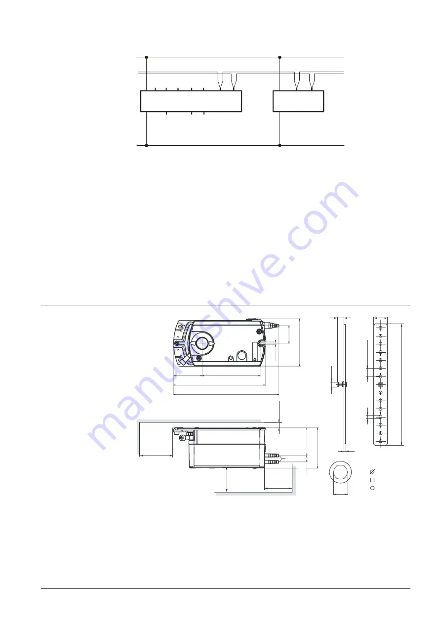
Dimensions

min. 100

m

in

.

20

0

min. 80

m

in

.6

8

20

ø

7

2

5

18

0

X

8 - 16 mm
12.8 mm
15 mm

3547M01

14

x

1

2

X =

4.

1

5

7

1

2

6.

5

87

158

137

Ø 3...8

43

41

.3

61

9.

6

Measurements in mm

Wiring diagram VAV

Connection to the KNX
TP1-Bus

Application examples

Note

Содержание OpenAir E Series

Страница 1: ...gitally configurable air volume controller Operating voltage AC 24 V Nominal torque 5 or 10 Nm air damper angular rotation can be adjusted mechanically from 0 to 90 Can be configured as a stand alone device per room or cascade control 1 1 pressure ratios positive or negative pressure Pre wired with a 0 9 meter power cable and 0 9 meter KNX cable Please refer to Technical Basics P3547 for a compreh...

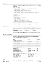
Страница 2: ...urated with sticky or fatty particles or contain aggressive substances Type summary Type Torque Application range Operating voltage GDB181 1E KN 5 Nm 0 300 Pa AC 24 V GLB181 1E KN 10 Nm 0 300 Pa AC 24 V Please refer to data sheet N4698 for information on accessories and spare parts Equipment combinations VAV compact controllers are KNX certified and may be connected to all KNX devices compatible w...

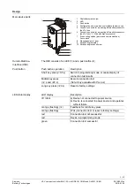
Страница 3: ...e check screw The HMI consists of an LED 1 and a push button 2 LED display Description off dark a Device not connected to power source b Device is connected to power source and operates without failure orange flashing 1x Feedback for middle key press orange flashing Wait connection test or reset to factory settings red Connection test not successful red Device in programming mode green Connection ...

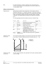
Страница 4: ...sioning Parameter Setting Description Siemens factory setting n V 1 3 16 Characteristic value for the air volume flow set by the manufacturer OEM 1 max V 20 120 Maximum air volume flow 100 min V 20 100 Minimum air volume flow 0 Dir r or L Air damper rotation opening direction r Clockwise CW L Counter clockwise CCW r ADP Off or on Standard mode for air damper position display Mapping 0 90 0 100 Ada...

Страница 5: ...ling Power supply and bus cabling must be tested After power up the device can assume the following states State desired behavior User action Device response LED Functionality available in all system environments Power up device starts up Connect device to power supply LED is orange goes off after power up is completed Faultless operation none LED is off Set device to programming addressing mode S...

Страница 6: ...hines red b In ACS790 click button Programming mode Address assignment enter physical address click Write or a Select a VAV compact controller from the device list by ID IDs are collected during mounting b Double click the selected row to open the dialog box Address assignment Enter a physical address and short description for the selected VAV compact controller Click Write to close dialog box Rep...

Страница 7: ...ion cable Cable length 0 9 m Number of cores and cross sectional area 2 x 0 75 mm 2 Degree of protection and safety class Degree of protection acc to EN 60529 Refer to mounting instruction IP54 Safety class acc to EN 60730 III Environmental conditions Operation transport IEC 721 3 3 IEC 721 3 2 Temperature 0 50 C 25 70 C Humidity non condensing 95 r h 95 r h Standards and Regulations Product safet...

Страница 8: ...he product environmental declaration contains data on environmentally compatible product design and assessments RoHS compliance materials composition packaging environmental benefit disposal Internal diagrams The VAV compact controller is supplied with two prewired connecting and communication cables All interconnected devices must be connected to the same G0 p G CE CE 1 1 2 G0 2 3547G01 Tool Tool...

Страница 9: ...th twin terminals or internally connected terminals may be encountered as well as bus connection in junction boxes Please refer to the technical basic documentation for product specific information The operating voltage at terminals G and G0 must comply with the requirements under SELV or PELV Safety transformers with twofold insulation as per EN 61558 required they must be designed to be on 100 o...

Страница 10: ...logies 2016 01 29 Issued by Siemens Switzerland Ltd Building Technologies Division International Headquarters Gubelstrasse 22 6301 Zug Switzerland Tel 41 41 724 24 24 www siemens com buildingtechnologies Siemens Switzerland Ltd 2011 Technical specifications and availability subject to change without notice ...

Отзывы: