3 / 10
Siemens
VAV compact controller KNX / PL-Link GDB181.1E/KN and GLB181.1E/KN
CE1N3547en
Building Technologies
2016-01-29
Design
2
3
4
5
8
9
10
3
54
7
J0
1
6
1
7
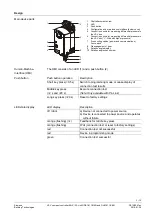
1 Shaft attachment screw
2 LED
3 Push button
4 Configuration and maintenance interface (below cover)
5
Connection nozzle for measuring differential pressure in
the VAV box
6
Connection nozzle for measuring differential pressure in
the VAV box ("+": Side with higher pressure)
7 2 connecting cables (power and communications),
2-core
each
8 Disengagement of gear
9 Rotation angle display
10 Rotation angle check screw
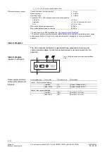
The HMI consists of an LED (1) and a push button (2).
LED display
Description
off / dark
a) Device not connected to power source
b) Device is connected to power source and operates
without failure
orange (flashing)
(1x)
Feedback for middle key press
orange (flashing)
Wait (connection test or reset to factory settings)
red
Connection test
not
successful
red
Device in programming mode
green
Connection test successful
Main device parts
Human-Machine-
Interface (HMI)
Push button
Push button operation
Description
Short key press (<0.5 s)
Switch to programming mode or cease display of
connection test results
Middle key press
(>2 s and <20 s)
Execute connection test
(Note: Only available with PL-Link)
Long key press (>20 s)
Reset to factory settings
LED state display

