


Diagnosing and troubleshooting
10.4 Noise problems
HydroRanger 200 HMI
286
Operating Instructions, 06/2018, A5E36281317-AC
Symptom
cause
Action
Displays Error and
tb:(#).
Wrong transducer selected
Verify transducer type and re-enter value.
Transducer connected in
“two-wire” method.
Do not tie white and shield together. Use all
three terminal blocks.
Transducer connected
backwards.
Reverse black and white wires on terminal
block.
Displays EEEE
Value too large to display
in 4 or 5 characters.
Select larger units [ Units (2.1.1.) (Page 162)],
or lower convert reading [Convert reading
Reading fluctuates
while material level is
still (or vice versa).
Incorrect measurement
stabilization.
Alter rate of response [Response rate (2.3.4.)
(Page 174)] or rate filter [Rate filter (2.3.5.)
(Page 175)] accordingly.
Reading is fixed, re-
gardless of the actual
material level.
Transducer acoustic beam
obstructed, standpipe too
narrow, or transducer
ringing (reads over 100%).
Relocate and / or re-aim transducer at materi-
al level or object.
Proceed to Measurement difficulties
(Page 289).
Material level reported
is always incorrect by
the same amount.
Incorrect empty (zero)
reference for level opera-
(Page 163) = *Level].
See Empty (2.2.4.) (Page 170), Offset reading
(2.12.6.) (Page 238), Sensor offset (2.2.5.)
(Page 171), Offset correction (2.11.1.9.)
(Page 221)
Measurement accuracy
improves as level nears
transducer.
Incorrect Sound Velocity
used for distance calcula-
tion.
Use a transducer with a built-in temperature
sensor or a TS-3 temperature sensor.
See Sound velocity (2.11.1.2.) (Page 218).
Reading is erratic, with
little or no relation to
material level.
True echo too weak or
wrong echo being pro-
cessed.
Relocate and/or re-aim transducer at material.
Check noise parameters. See Noise problems
(Page 286).
10.4
Noise problems
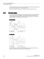
Incorrect readings can be the result of noise problems, either acoustic or electrical, in the
application. The noise present at the input to the ultrasonic receiver can be determined by
viewing the echo profile locally via the HMI, or alternatively, using remote software such
SIMATIC PDM. View also parameters Noise Average (3.2.11.5.) (Page 263) and Noise Peak
(3.2.11.6.) (Page 263). In general, the most useful value is the average noise.
With no transducer attached the noise is under 5 dB. This is often called the noise floor. If
the value with a transducer attached is greater than 5 dB, signal processing problems can
occur. High noise decreases the maximum distance that can be measured. The exact
relationship between noise and maximum distance is dependent on the transducer type and
the material being measured. An average noise level greater than 30 dB may be cause for
concern if the installed transducers maximum operation range matches the range of the
application (e.g. 8 m application using an 8 m XRS-5). Using a larger transducer with greater
transmitted energy should help to improve performance in a noise condition.
Содержание HydroRanger 200 HMI
Страница 2: ......
Страница 20: ...Introduction 1 5 Notes on warranty HydroRanger 200 HMI 18 Operating Instructions 06 2018 A5E36281317 AC ...
Страница 24: ...Safety notes HydroRanger 200 HMI 22 Operating Instructions 06 2018 A5E36281317 AC ...
Страница 28: ...Description 3 5 Modbus communication HydroRanger 200 HMI 26 Operating Instructions 06 2018 A5E36281317 AC ...
Страница 159: ...Parameter reference 8 2 Parameter indexing HydroRanger 200 HMI Operating Instructions 06 2018 A5E36281317 AC 157 ...
Страница 276: ...Parameter reference 8 10 Language 6 HydroRanger 200 HMI 274 Operating Instructions 06 2018 A5E36281317 AC ...
Страница 322: ...Pump control reference B 13 Other pump controls HydroRanger 200 HMI 320 Operating Instructions 06 2018 A5E36281317 AC ...
Страница 352: ...Communications C 41 Single parameter access SPA HydroRanger 200 HMI 350 Operating Instructions 06 2018 A5E36281317 AC ...
Страница 354: ...Updating software HydroRanger 200 HMI 352 Operating Instructions 06 2018 A5E36281317 AC ...
Страница 359: ...HydroRanger 200 HMI Operating Instructions 06 2018 A5E36281317 AC 357 Conduit entry for Class I Div 2 applications F ...
Страница 360: ...Conduit entry for Class I Div 2 applications HydroRanger 200 HMI 358 Operating Instructions 06 2018 A5E36281317 AC ...
Страница 361: ...Conduit entry for Class I Div 2 applications HydroRanger 200 HMI Operating Instructions 06 2018 A5E36281317 AC 359 ...
Страница 362: ......
Страница 372: ...Programming chart G 1 Programming chart HydroRanger 200 HMI 370 Operating Instructions 06 2018 A5E36281317 AC ...
Страница 390: ...LCD menu structure H 1 LCD Menu Structure HydroRanger 200 HMI 388 Operating Instructions 06 2018 A5E36281317 AC ...
Страница 403: ......