Diagnosing and troubleshooting
10.3 Common problems chart
HydroRanger 200 HMI
284
Operating Instructions, 06/2018, A5E36281317-AC
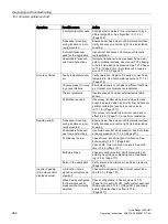
Symptom
Possible cause
Action
Incorrect Algorithm used Set algorithm to default. If no improvement, try a
different algorithm. See Algorithm (2.11.2.2.)
(Page 222).
Transducer mounting:
wrong location or incor-
rectly mounted
Ensure beam has a clear path to material surface;
Verify transducer is not too tight; Use an isolation
coupling.
Incorrect transducer
used for the application
Use correct transducer. Contact your Siemens
representative.
Unavoidable false ech-
oes from obstructions
Relocate transducer to ensure beam has a clear
path to material surface; Use manual TVT shaping
or Auto False Echo Suppression. See TVT Shaper
(2.11.4.) (Page 231) or Auto false echo suppres-
sion (2.11.3.2.) (Page 227).
Accuracy Varies
Faulty temperature sen-
sor
Verify operation; Replace if required, or use fixed
temperature. See Temperature source (2.11.1.4.)
(Page 219).
Vapours present in vary-
ing concentrations
Eliminate vapours or consider a different technolo-
gy. Contact your Siemens representative.
Thermal gradients
Insulate vessel; Consider external temperature
sensor.
Calibration required
If accuracy is better when level is close to trans-
ducer, and worse when level is far from transducer,
perform calibration [see Auto sound velocity
(2.11.1.8.) (Page 221)].
If accuracy is consistently incorrect, use Sensor
offset (2.2.5.) (Page 171) or perform calibration.
Reading erratic
Transducer mounting:
wrong location or incor-
rectly mounted
Ensure beam has a clear path to material surface;
Verify transducer is not too tight; Use an isolation
coupling.
Unavoidable false ech-
oes from obstructions
Use Auto False Echo Suppression. See Auto false
echo suppression (2.11.3.2.) (Page 227).
Confidence too low
Check Noise, Echo Strength, Confidence. See
Echo quality (3.2.11.) (Page 262).
Check LOE Timer is not set too short. See LOE
timer (2.4.2.) (Page 177).
Multiple echoes
Check mounting location; Verify material is not
entering near range or blanking zone. See Blank-
ing (2.2.6.) (Page 171).
Noise in the application Verify source and minimize. See Noise problems
(Page 286).
Incorrect reading
(mA output and/or
displayed value)
mA function not as-
signed to correct meas-
urement
Check mA assignment. See Current output func-
tion (2.5.3.) (Page 181).
When device configured
for flow: exponent or
breakpoint not correctly
selected
Check configuration: if Sensor mode (2.1.3.)
(Page 163) is set to FLOW, verify correct exponent
[Flow exponent (2.13.4.1) (Page 241)] and break-
points [Universal head vs flow (2.13.6.)
(Page 247)].
Содержание HydroRanger 200 HMI
Страница 2: ......
Страница 20: ...Introduction 1 5 Notes on warranty HydroRanger 200 HMI 18 Operating Instructions 06 2018 A5E36281317 AC ...
Страница 24: ...Safety notes HydroRanger 200 HMI 22 Operating Instructions 06 2018 A5E36281317 AC ...
Страница 28: ...Description 3 5 Modbus communication HydroRanger 200 HMI 26 Operating Instructions 06 2018 A5E36281317 AC ...
Страница 159: ...Parameter reference 8 2 Parameter indexing HydroRanger 200 HMI Operating Instructions 06 2018 A5E36281317 AC 157 ...
Страница 276: ...Parameter reference 8 10 Language 6 HydroRanger 200 HMI 274 Operating Instructions 06 2018 A5E36281317 AC ...
Страница 322: ...Pump control reference B 13 Other pump controls HydroRanger 200 HMI 320 Operating Instructions 06 2018 A5E36281317 AC ...
Страница 352: ...Communications C 41 Single parameter access SPA HydroRanger 200 HMI 350 Operating Instructions 06 2018 A5E36281317 AC ...
Страница 354: ...Updating software HydroRanger 200 HMI 352 Operating Instructions 06 2018 A5E36281317 AC ...
Страница 359: ...HydroRanger 200 HMI Operating Instructions 06 2018 A5E36281317 AC 357 Conduit entry for Class I Div 2 applications F ...
Страница 360: ...Conduit entry for Class I Div 2 applications HydroRanger 200 HMI 358 Operating Instructions 06 2018 A5E36281317 AC ...
Страница 361: ...Conduit entry for Class I Div 2 applications HydroRanger 200 HMI Operating Instructions 06 2018 A5E36281317 AC 359 ...
Страница 362: ......
Страница 372: ...Programming chart G 1 Programming chart HydroRanger 200 HMI 370 Operating Instructions 06 2018 A5E36281317 AC ...
Страница 390: ...LCD menu structure H 1 LCD Menu Structure HydroRanger 200 HMI 388 Operating Instructions 06 2018 A5E36281317 AC ...
Страница 403: ......


