Parameter reference
8.6 Setup (2.)
HydroRanger 200 HMI
Operating Instructions, 06/2018, A5E36281317-AC
219
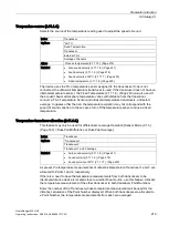
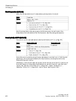
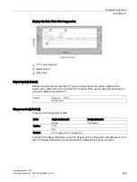
Temperature source (2.11.1.4.)
Selects the source of the temperature reading used to adjust the speed of sound.
Index
Transducer
Options
*AUTO
Fixed Temperature
Transducer
External TS-3
Average of Sensors
Alters
Process temperature (2.11.1.3.) (Page 218)
Related
•
Auto sound velocity (2.11.1.8.) (Page 221)
•
Sound velocity (2.11.1.2.) (Page 218)
•
Sound velocity at 20°C (2.11.1.7.) (Page 220)
•
Fixed temperature (2.11.1.6.) (Page 220)
The device uses the TS-3 temperature sensor assigned to the transducer. If one is not
connected, the ultrasonic/temperature transducer is used. If the transducer does not have an
internal temperature sensor, the Fixed Temperature (2.11.1.6.) (Page 220) value is used. If
the acoustic beam atmosphere temperature varies with distance from the transducer,
connect a TS-3 Temperature Sensor and ultrasonic/temperature transducers, and select
average. In gasses other than air, the temperature variation may not correspond with the
speed of sound variation. In these cases, turn off the temperature sensor and use a fixed
temperature.
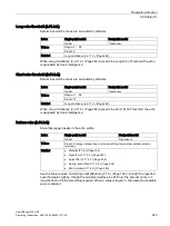
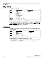
Temperature transducer allocation (2.11.1.5.)
This feature may only be used for differential or average Operation [Sensor Mode (2.1.3.)
(Page 163) = Dual-Point Difference or Dual-Point Average].
Index
Transducer
Options
*Transducer 1
Transducer 2
Transducer 1 and 2 average
Related
•
Auto sound velocity (2.11.1.8.) (Page 221)
•
Sound velocity (2.11.1.2.) (Page 218)
•
Sound velocity at 20°C (2.11.1.7.) (Page 220)
As preset, the temperature measurements of ultrasonic/temperature Transducer 1 and 2 are
allocated to Points 1 and 2, respectively.
If there is a need to have the temperature measurements from both transducers to be
identical while one device is located close to a radiant heat source, use this feature. Allocate
the temperature measurement of the other transducer to both transducer Point Numbers.
Enter the number of the Transducer whose temperature measurement will be used for the
distance calculation of the Point Number displayed. When both transducers are allocated to
a Point Number, the temperature measurements from each are averaged.
Содержание HydroRanger 200 HMI
Страница 2: ......
Страница 20: ...Introduction 1 5 Notes on warranty HydroRanger 200 HMI 18 Operating Instructions 06 2018 A5E36281317 AC ...
Страница 24: ...Safety notes HydroRanger 200 HMI 22 Operating Instructions 06 2018 A5E36281317 AC ...
Страница 28: ...Description 3 5 Modbus communication HydroRanger 200 HMI 26 Operating Instructions 06 2018 A5E36281317 AC ...
Страница 159: ...Parameter reference 8 2 Parameter indexing HydroRanger 200 HMI Operating Instructions 06 2018 A5E36281317 AC 157 ...
Страница 276: ...Parameter reference 8 10 Language 6 HydroRanger 200 HMI 274 Operating Instructions 06 2018 A5E36281317 AC ...
Страница 322: ...Pump control reference B 13 Other pump controls HydroRanger 200 HMI 320 Operating Instructions 06 2018 A5E36281317 AC ...
Страница 352: ...Communications C 41 Single parameter access SPA HydroRanger 200 HMI 350 Operating Instructions 06 2018 A5E36281317 AC ...
Страница 354: ...Updating software HydroRanger 200 HMI 352 Operating Instructions 06 2018 A5E36281317 AC ...
Страница 359: ...HydroRanger 200 HMI Operating Instructions 06 2018 A5E36281317 AC 357 Conduit entry for Class I Div 2 applications F ...
Страница 360: ...Conduit entry for Class I Div 2 applications HydroRanger 200 HMI 358 Operating Instructions 06 2018 A5E36281317 AC ...
Страница 361: ...Conduit entry for Class I Div 2 applications HydroRanger 200 HMI Operating Instructions 06 2018 A5E36281317 AC 359 ...
Страница 362: ......
Страница 372: ...Programming chart G 1 Programming chart HydroRanger 200 HMI 370 Operating Instructions 06 2018 A5E36281317 AC ...
Страница 390: ...LCD menu structure H 1 LCD Menu Structure HydroRanger 200 HMI 388 Operating Instructions 06 2018 A5E36281317 AC ...
Страница 403: ......

