Parameter reference
8.6 Setup (2.)
HydroRanger 200 HMI
Operating Instructions, 06/2018, A5E36281317-AC
177
8.6.4
Fail-safe (2.4.)
The fail-safe parameters ensure that the devices controlled by the main device default to an
appropriate state when a valid level reading is not available. The Primary Reading region on
the HMI will display dashes (– – – – ) until the fail-safe fault has been cleared.
For a list of faults that will cause fail-safe, see General fault codes (Page 282).
Note
When a Loss of Echo occurs, Material Level (2.4.5.) (Page 178) determines the material
level to be reported when the fail-safe timer expires. For more details, see Fail-safe mode
(Page 312).
8.6.4.1
Transducer selector (2.4.1.)
Sets the transducer index for all parameters applicable to this sub-menu.
8.6.4.2
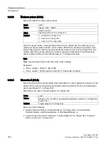
LOE timer (2.4.2.)
The time for invalid measurements to elapse before a fail-safe state activates.
Index
Single-point model
Dual-point model
Global
Transducer
Values
Range: 0 ... 15 minutes
Preset 10.00 minutes
Altered by
Response rate (2.3.4.) (Page 174)
Related
Relay fail-safe (2.8.2.3.) (Page 201)
Once activated, the fail-safe state initiates the following:
1.
The material level is reported based on Material level (2.4.5.) (Page 178)
–
The unit responds to the new level as programmed (control and alarm relays activate
as defined by the programming).
–
Individual relays can have independent fail-safe responses. See Relay fail-safe
(2.8.2.3.) (Page 201).
2.
The appropriate error is displayed:
–
LOE for loss of echo from the transducer.
–
Short for a shorted transducer cable.
–
Open for a cut transducer cable.
–
Error for all other problems.
When modifying the preset value, set it short enough to protect the process, but long enough
to avoid false alarms. Only use 0.0 minutes (no delay) for testing.
Содержание HydroRanger 200 HMI
Страница 2: ......
Страница 20: ...Introduction 1 5 Notes on warranty HydroRanger 200 HMI 18 Operating Instructions 06 2018 A5E36281317 AC ...
Страница 24: ...Safety notes HydroRanger 200 HMI 22 Operating Instructions 06 2018 A5E36281317 AC ...
Страница 28: ...Description 3 5 Modbus communication HydroRanger 200 HMI 26 Operating Instructions 06 2018 A5E36281317 AC ...
Страница 159: ...Parameter reference 8 2 Parameter indexing HydroRanger 200 HMI Operating Instructions 06 2018 A5E36281317 AC 157 ...
Страница 276: ...Parameter reference 8 10 Language 6 HydroRanger 200 HMI 274 Operating Instructions 06 2018 A5E36281317 AC ...
Страница 322: ...Pump control reference B 13 Other pump controls HydroRanger 200 HMI 320 Operating Instructions 06 2018 A5E36281317 AC ...
Страница 352: ...Communications C 41 Single parameter access SPA HydroRanger 200 HMI 350 Operating Instructions 06 2018 A5E36281317 AC ...
Страница 354: ...Updating software HydroRanger 200 HMI 352 Operating Instructions 06 2018 A5E36281317 AC ...
Страница 359: ...HydroRanger 200 HMI Operating Instructions 06 2018 A5E36281317 AC 357 Conduit entry for Class I Div 2 applications F ...
Страница 360: ...Conduit entry for Class I Div 2 applications HydroRanger 200 HMI 358 Operating Instructions 06 2018 A5E36281317 AC ...
Страница 361: ...Conduit entry for Class I Div 2 applications HydroRanger 200 HMI Operating Instructions 06 2018 A5E36281317 AC 359 ...
Страница 362: ......
Страница 372: ...Programming chart G 1 Programming chart HydroRanger 200 HMI 370 Operating Instructions 06 2018 A5E36281317 AC ...
Страница 390: ...LCD menu structure H 1 LCD Menu Structure HydroRanger 200 HMI 388 Operating Instructions 06 2018 A5E36281317 AC ...
Страница 403: ......


