$SSHQGL[(
$S
$SSSHHQQGL[ (
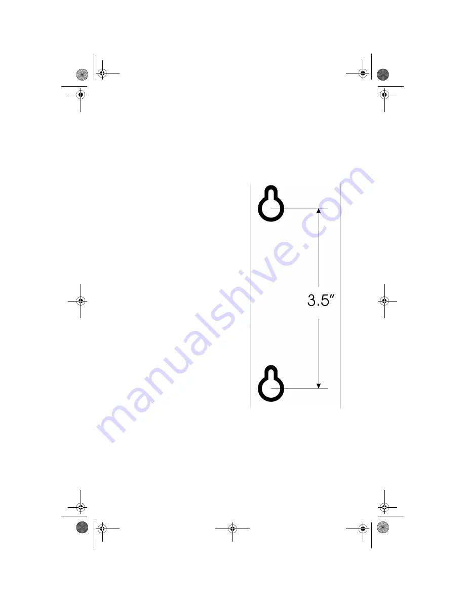
GL[ ( Wall Mounting Template
63
(
:DOO0RXQWLQJ7HPSODWH
Be sure to mount the base control-
ler so that its power supply plug can
reach an electrical outlet.
1. Drill two holes vertically 3.5 in.
(8.89 cm) apart into a non-
metal wall. You can use this
page as a template. Avoid elec-
trical wiring.
2. Remove the wall mount kit
from the system box.
3. Insert the screw inserts into
the holes and turn the screws
until there is a gap of approxi-
mately 3 mm between the
head of the screw and the wall.
4. Slide the base controllers
mounting slots onto the
screws.
5. Plug the power supply into a
functional 110 volt electrical
outlet not controlled by a wall
switch.
Gigaset 2402.book Seite 63 Dienstag, 6. Juli 1999 5:53 17


