General Information
1.6 Function 04: Read Input Register
ATC5300
Modbus Communication Protocol, Edition 03/2011, A5E02469001-02
9
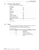
The ATC answer is the following:
Where:
01 = ATC address (Slave 01)
04 = Function requested by the master
04 = Number of bytes sent by the ATC
00 00 00 7C = Hex value of the battery voltage = 124 = 12.4 VDC
FA 65 = CRC checksum
1.6
Function 04: Read Input Register
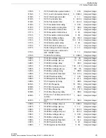
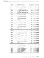
The Modbus® function 04 allows to read one or more consecutive registers from the slave
memory. The address of each measure is given in the chapter "Data Library" of this manual.
As for Modbus® standard, the address in the query message must be decreased by one from
the effective address reported in the table. If the measure address is not included in the table
or the number of requested registers exceeds 60, the ATC will return an error code (see error
table).
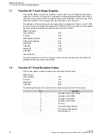
Master query:
In the above example slave 08 is requested for 8 consecutive registers beginning with address
10h. Thus, registers from 10h to 17h will be returned. As usual, the message ends with the
CRC checksum.
Slave response:
The response is always composed of the slave address, the function code requested by the
master and the contents of the requested registers. The answer ends with the CRC.
01
04
04
00
00
00
7C
65
Slave address
08h
Function
04h
MSB address
00h
LSB address
0Fh
MSB register number
00h
LSB register number
08h
MSB CRC
21h
LSB CRC
57h
Slave address
08h
Function
04h
Byte number
10h
MSB register 10h
00h
LSB register 10h
00h
—
—
MSB register 17h
00h
LSB register 17h
00h
MSB CRC
5Eh
LSB CRC
83h


