


A wide range of options are
available for integrating WL
circuit breakers in automation
systems. New users will
appreciate the straightforward
and quick start-up options,
while experienced users will
find that the flexible options
meet their requirements.
Communication Options
The PROFIBUS COM15 module
acts as an interface between the
circuit breakers and the information
environment. A joint device master
file (GSD) can be used for integration
in PROFIBUS-DP systems for all
WL circuit breakers. A distinction
between individual breakers and/or
frame ratings cannot and does not
have to be drawn. Of course, with
an identical PROFIBUS-DP profile, the
circuit breaker that is addressed can
be accurately identified (e.g. device
description order number, inspection
date, etc.).
PROFIBUS Communication
Integration into an Automation System
3/1
WL Circuit Breaker
Graphic
3-1
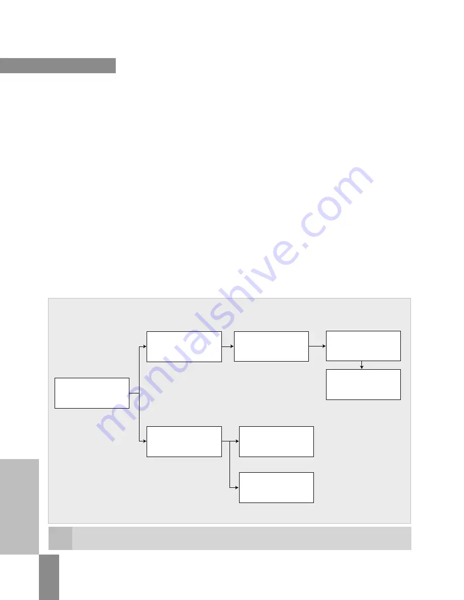
This diagram shows a chart of the different communication options. A class 1 master is the “configuration master,” which transmits either
the settings from the GSD file to the slave during start-up.
Parameterization,
operation, monitoring,
diagnosis via DPV1 C+M
system (e.g. WinCC)
Parameterization,
operation, monitoring,
diagnosis via DPV1 with
an additional PLC
PROFIBUS-DP
communication with
WL circuit breakers
Communication
with the PLC / PC
(class 1 master)
Communication
with the PLC / PC
(class 2 master)
Optional access
via DPV1
Connection as
standard DP slave
Configuration with
GSD file and
master-specific tool
WL PROFIBUS Communication and Electronic Accessories • July 2004


