


Short-circuit at 1:
Only -Q1 establishes that a short-
circuit has occurred and does not
receive a blocking signal from a
subordinate level. For this reason,
it trips after t
ZSI
= 50 ms. Time
saved = 250 ms.
The ZSI function can be used for
short-circuits between the phases
(S), with respect to ground (G),
or for both simultaneously (S+G).
The operating mode is set using the
rotary switch. If the switch is in the
“OFF” position, the ZSI is deactivated.
The ZSI module also provides the
blocking signal for the medium-
voltage level.
If a tie breaker is used in the power
distribution system, this can also be
equipped with the ZSI function and
integrated in the overall concept.
Up to 8 circuit breakers can be
connected to ZSI IN, and up to 20
to ZSI OUT.
Attention:
Proper performance
cannot be guaranteed if these
limits are exceeded.
The ZSI module must always be the
first external
Cubicle
BUS
module to
be connected to the COM15 module
or to X8.
Test function
The outputs are set (i.e. a blocking
signal is sent to other circuit
breakers) when the rotary switch
is set to “TEST.”
Pressing the “TEST” key switches the
ZSI module to test mode, which is
indicated by the yellow DEVICE LED.
The inputs and outputs are selected
in the same way as the digital
input/output modules. When the ZSI
module input is selected, the input
can be toggled internally by pressing
and releasing the TEST key. When the
outputs are selected, the outputs can
be toggled by pressing and releasing
the TEST key. This enables the circuit
to be checked.
Active inputs and outputs are
indicated by a yellow LED.
It is recommended that the ZSI signal
be transmitted via a shielded twisted
pair with a cross-section of at least
0.75 mm
2
(18 AWG), and no more
than 400 m long.
Communication-capable Circuit Breakers
2/31
Operating voltage min. / max.
19.2V / 28.8V
Operating current min. / max.
31mA / 61mA
Automatic output reset after no more than...
3 s
Shortest time blocking signal can be present at the outputs LV
100 ms
Shortest time blocking signal can be present at the outputs MV 500 ms
Standard trip time (incl. all delays)
approx. 80 ms
Max. no. of circuit breakers connectable to ZSI IN
20
Max. no. of circuit breakers connectable to ZSI OUT
8
Max. no. of modules on one WL Circuit Breaker
1
Max. wire length for 2 x 18 AWG twisted pair
400 m
Power loss min. / max.
0.8W / 1.76W
Dimensions W / H / D
70
mm
/86
mm
/95
mm
Weight
0.223 kg
Operating temperature range
-20°C / 60°C
Technical data for the ZSI module
Table 2-22
This table provides technical data for the ZSI module on the
Cubicle
BUS
.
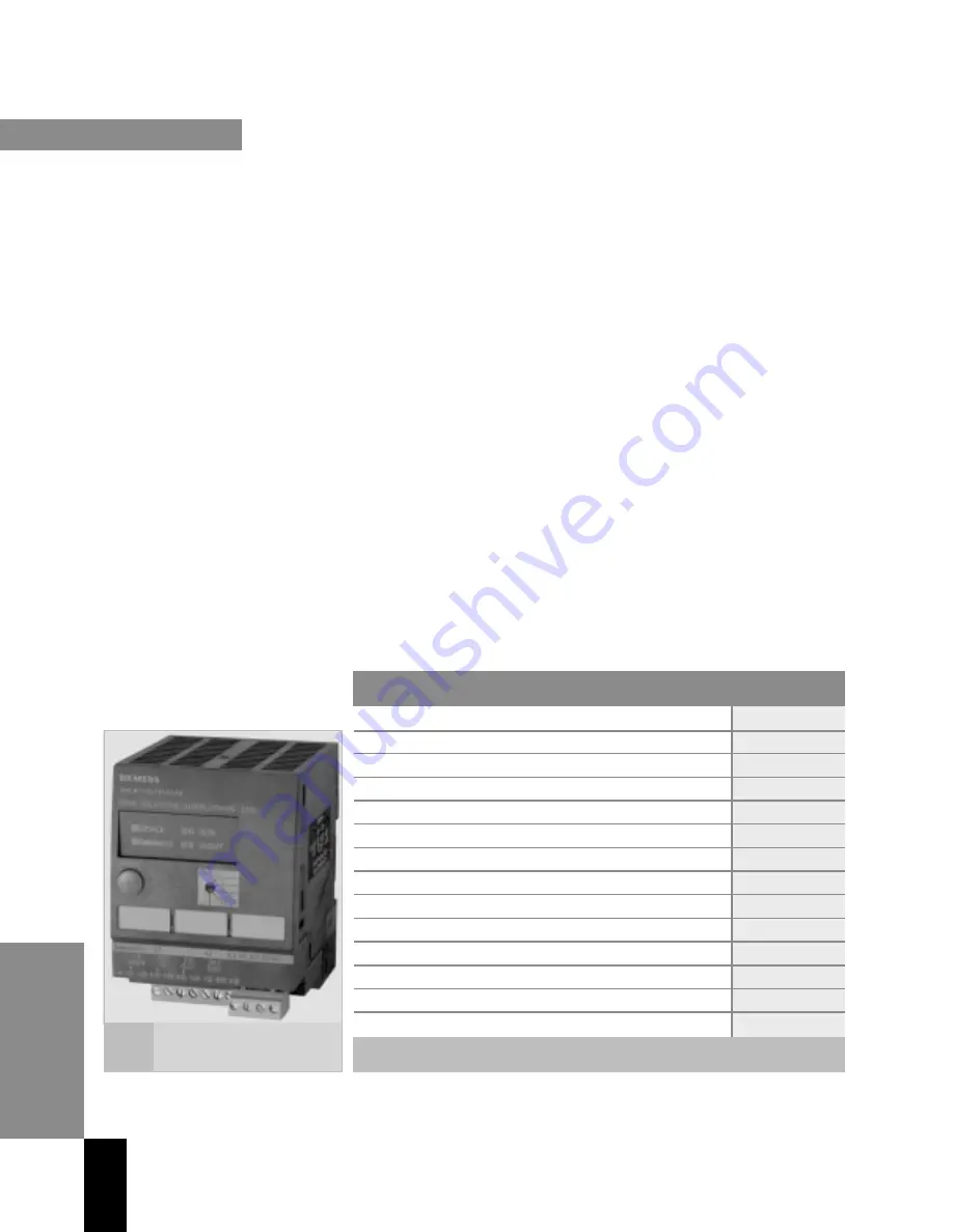
WL Circuit Breaker
The function of the ZSI
module is selected using the
rotary switch.
Figure
2-17
WL PROFIBUS Communication and Electronic Accessories • July 2004


