


Building Technologies
74 319 0618 0 a
17.04.2008
58/276
en
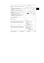
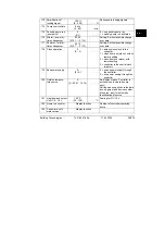
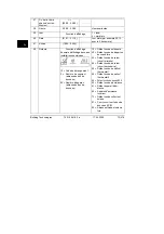
166 Resulting heating
curve
Display function
Setpoint incl. setting knob position
and setting on operating line 72
Left:
Flow setpoint at 15 °C out-
side temperature
Right:
Flow setpoint at –5 °C
outside temperature
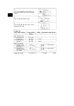
167 Outside temp. for
frost protection for
the plant
2.0 °C
(--.- / 0…25)
...................
°C
Setting --.- = no frost protection for
the plant
168 Flow temp. setpoint
for frost protection
for the plant
15 °C
(0…140)
...................
°C
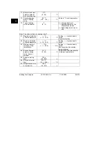
169 Device
number
0
(0…16)
.........................
Data bus address (LPB)
0 = device with no bus
170 Segment
number
0
(0…14)
.........................
Data bus address (LPB)
171 Flow
alarm
--:-- h
(--:-- / 1:00…10:00)
......................
h
Period of time during which the
flow / boiler temperature (sensor
at terminal B1) may stay outside
the limit values
--.-- = function deactivated
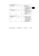
Space heating mode
D.h.w.
0 =
PROTECTION
OFF
1 =
AUTO OFF
2 =
REDUCED OFF
3 =
NORMAL OFF
4 =
PROTECTION
ON
5 =
AUTO ON
6 =
REDUCED ON
7 =
NORMAL ON
8 =
AUTO
ON,
24 h / day
172 Operating
mode
when terminals H1–
M are linked
0
(0…9)
.........................
9 =
NORMAL
ON,
24 h / day