


Start-Up
09.02
4-20
Siemens AG 6SE7087-6AK85-1AA0
Rectifier/Regenerating Unit Operating Instructions
Bit 9: Inching 2 OFF command (L "Inching 2 OFF")
The command is executed with an L signal.
After the command has been accepted:
♦
An OFF 1 command is automatically executed (description, refer to control word bit 0).
Bit 10: Control from the PLC command (H "Control from the PLC")
The command is executed with an H signal
Process data PZD (control word, setpoints) originating from a PLC which were sent via the SST1 interface of
CU1, the CB/TB interface (option) and the SST/SCB interface (option), are only evaluated if the command was
accepted.
♦
If several interfaces are operational, only the process data of the interfaces are evaluated, which transmit the
H signal.
♦
For an L signal, the last values are retained in the appropriate dual port RAM of the interface.
An H signal appears in the visualization parameter r550 "control word 1", if one of the interfaces transmits an H
signal!
Bit 11: Ud reduction command (H "Ud reduction requested")
(See also Chapter 4.3.10.2)
The command is executed with an H signal.
After the command has been accepted:
♦
The DC link voltage setpoint drops to the value set with P318:
%
00
.
100
318
P
U
35
.
1
int
Setpo
*
*
rectifier
,
Supply
=
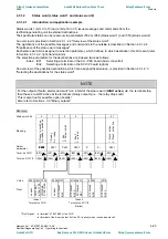
If the value of P330 is even, Ud setpoint lowering takes place abruptly. If it is odd, the setpoint is ramped
down according to the discharge time in P330.
♦
At the same time, the intermediate DC link voltage threshold for enabling the regenerating bridge is reduced
to the following value if an autotransformer is not present (i.e. when
17
.
1
U
U
rectifier
,
Supply
ng
regenerati
,
Supply
<
):
%
00
.
100
318
P
U
35
.
1
*
*
ng
regenerati
,
Supply
This causes the signal "Regenerating ready" (status word 1, bit 10) to switch to low.
♦
The DC link should now discharge.
♦
When the DC link voltage drops below the following threshold value
071
P
35
.
1
%
100
%
2
%
00
.
100
318
P
U
35
.
1
*
*
*
*
rectifier
,
Supply
+
the message "Ud reduced" (status word 1, bit 13) is issued, and a converter connected to the DC link can
regenerate. At the same time as the message "Ud reduced" is issued, for which the hysteresis of P319
applies, the regenerating bridge is enabled such that the DC link voltage threshold for the message
"Regenerating ready" is set to a higher value.
♦
The appearance of a trailing edge of the Ud reduction command causes the output of the ramp-up/return
element (precharging time P329) to be set to the current value of DC link voltage so that the DC link voltage
setpoint can ramp up again from this value.
♦
The L signal of the Ud reduction command causes the "Ud reduced" message (status word 1, bit 13) to be
held low (regardless of the DC link voltage level)
https://www.aotewell.com
AoteWell Automation Sales Team
Sales@aotewell.com
AoteWell LTD
Buy Siemens PLC HMI Drives at AoteWell.com
https://www.aotewell.com


