Siemens IK PI · 2004
6/106
AS-Interface Slaves
AS-Interface compact starters IP65 (400 V AC)
AS-Interface motor starters and IP65/67 load feeders
6
■
Design
(continued)
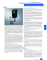
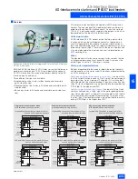
The load itself and any other compact starters are supplied us-
ing the same connection technique. All the supply and data ca-
bles can thus be laid through the system like a bus. Whereas the
controlgear is switched via the outputs by the 24 V auxiliary
power supply, the inputs are supplied by the AS-Interface data
cable. This principle of separate auxiliary power supplies facili-
tates selective emergency stop concepts.
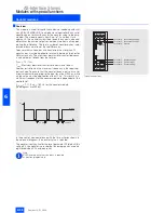
Addressing
The addressing of the AS-Interface compact starter can still be
used even if it is fully wired, because the module is disconnected
from the AS-Interface network as soon as the addressing con-
nector is inserted.
■
Function
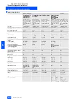
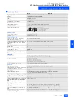
Display characteristics
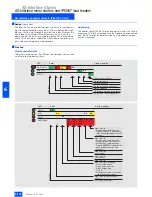
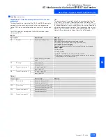
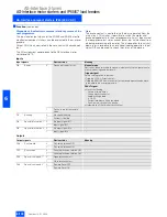
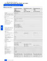
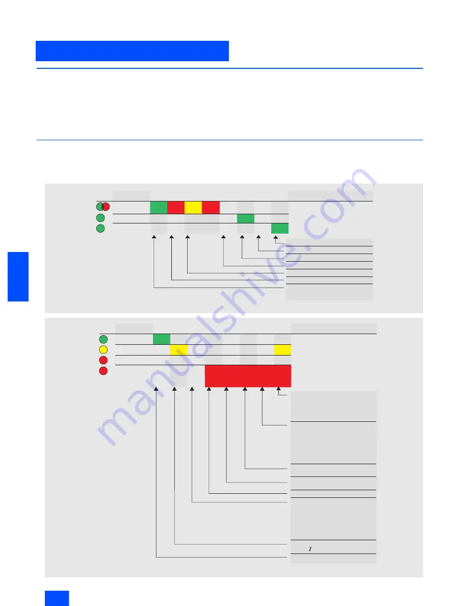
Under normal operation, the LEDs on the compact starters indi-
cate the following device states:
LED
AUX PWR
AS-Interface
STATE
1
)
NSA0_00322
Status description
Control signal applied
No auxiliary power
Auxiliary power on
No power for slave electronics
Station address 0
AS-Interface communication absent
AS-Interface communication o.k.
On
States
Flash-
ing
On
On
Flash-
ing
Off
On
Off
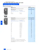
LED
RUN
READY
FAULT
NSA0_00323
OVERLOAD
States
Status description
Main circuit on
Rotary coding switch in position
Tripping REMOTE: Continued ope-
ration when programmed in the user
program
Main circuit off
Rotary coding switch in position
Tripping LOCAL: Direct shut-off
Rotary coding switch in position
Tripping REMOTE: Remote shut-off
when programmed in the user
program
Main circuit off
(test finished)
Main circuit off
(test running)
Main circuit on
Main circuit off, e.g. through
Failure of two phases
Drawn motor connector
Supply voltage drop
(< 18 V)
Simultaneous control of clockwise
and anti-clockwise rotation
Main circuit on with conduction
>_ 20%
n
Unit ready to operate
On
On
Off
On
On
Nor-
mal
flash-
ing
Fast
flash-
ing
Slow
flash-
ing
On
On

