


BAL XC420 2.00
13/47
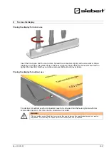
Use according proper mounting material if the screws and dowels included do not match.
The spacers, in combination with the screws, allow a fastening of the device with a distance of
approximately 10 mm to the wall.
The cables can then be fed between wall and device (surface mounting). To fix the spacers during
installation use the included hexagonal self-adhesive stripes.
Power supply connection
After mounting the device on the wall you connect the line for the power supply to the terminal. Make
sure that the 230V line was damaged nowhere during insertion into the device.
The unit has a metal housing. It corresponds with protection type I and needs a protective conductor
connection. The connecting cable for the power supply must contain a protective ground wire
connection with sufficient cross-section (DIN VDE 0106 Teil 1, DIN VDE 0411 part 1).
The protective ground wire (yellow/green) can be connected either to the yellow or the green terminal.
When first powered on numbers appear on all digits. Depending on the unit version, during later
power-up
– after implementing of the configuration – the decimal points light up.