7
4526
8
2020
-
SE IP 50
MC_0003
1
2
3
4
6
5
MG_0048
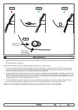
Increase tunnel length to protect
the propeller from water forces
when high-speed cruising.
Water
Forces
Increase tunnel length to prevent
a circular water vacuum cavity
between the propeller and the
hull of the boat.
STANDARD USE
FLAT BOTTOM HULL
HIGH-SPEED OPERATION
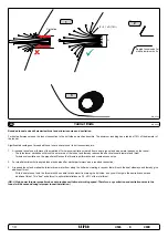
Do not allow the variable length of the tunnel walls to vary in length
excessively.
EG. the top tunnel wall is x 4 longer than the bottom wall.
Cavitation
Water flow must have
space to "straighten"
itself for best
performance.
The gear leg/ propeller(s) must
never extend out of the tunnel
Tunnel Length
EN
Optimal tunnel length
Achieving the correct tunnel length depends on many factors from the hull type, operation and environmental conditions.
Tunnels should avoid being longer than 4 x the tunnel diameter as this will reduce thruster performance.
(NB: Installing long length tunnels can fl ex/
bend over time and may require additional support. Consult with a naval architect.)
1. Do not allow the variable length of the tunnel walls to vary in length excessively.
EG. the top tunnel wall is x 4 longer than the bottom wall.
2. If the tunnel is too long, the friction inside will reduce the water speed and thereby the thrust.
3. If the tunnel is too short (typically only in the bottom section of the tunnel) cavitation problems can occur as water fl ow will not be able to
“straighten” itself before reaching the propeller. This cavitation will reduce performance and increase noise during operation.
Thruster within the tunnel
It is important the propellers and the lower unit/ gear leg must be entirely inside the thruster tunnel. Propellers that protrude from the tunnel will not
perform as intended.
4.
Standard Use
Tunnel length must be long enough to ensure the propellers are not extruding the tunnel.
5.
Flat Bottom Hull
Tunnel lengths must be longer than the standard measurement outlined within the manual to ensure a circular vacuum is not created between the
thruster and the bottom of the boat.
6.
High-Speed Boats
Tunnel lengths must be increased to protect the propeller from damage when crashing against the water surface during high-speed cruising.
(NB:
This can include the length of a spoiler)
important
MG_0001
A
B
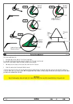
Pivot
point
1
Ø
2
Lowered rotation power performance
Stronger rotation power performance
min 1/4
Ø
(Recommended)
min 1/4
Ø
(Recommended)
WD
Water line
Positioning of the tunnel / thruster
EN
MC_0003
Aim to install the thruster as far forward as possible (1)
Due to the leverage eff ect around the boats’ pivot point. The distance diff erence from the boat pivots’ point to the thruster will determine the amount of
real rotation power for the boat.
Aim to install the thruster as deep as possible under the waterline (2)
Deeper installations prevent air from being sucked into the tunnel from the surface, resulting in reduced thrust performance and increase noise levels
during operation. Deeper installations increase water pressure for maximum effi ciency from the thruster.
The centre of the tunnel should be a minimum of 1 x the tunnel diameter below the waterline. The installer must make evaluations based on thruster
performance, boat type and operating conditions. As a general recommendation, the position of the tunnel should not be a minimum of 1/4 of the
diameter of the tunnel from the boat keel.
(NB: This can be overlooked depending on the installation methods defi ned in this manual.)
Содержание SE IP-140
Страница 26: ...26 4526 8 2020 SE IP 50 MC_0037 Notes EN ...
Страница 27: ...27 4526 8 2020 SE IP 50 MC_0037 Notes EN ...

