


•
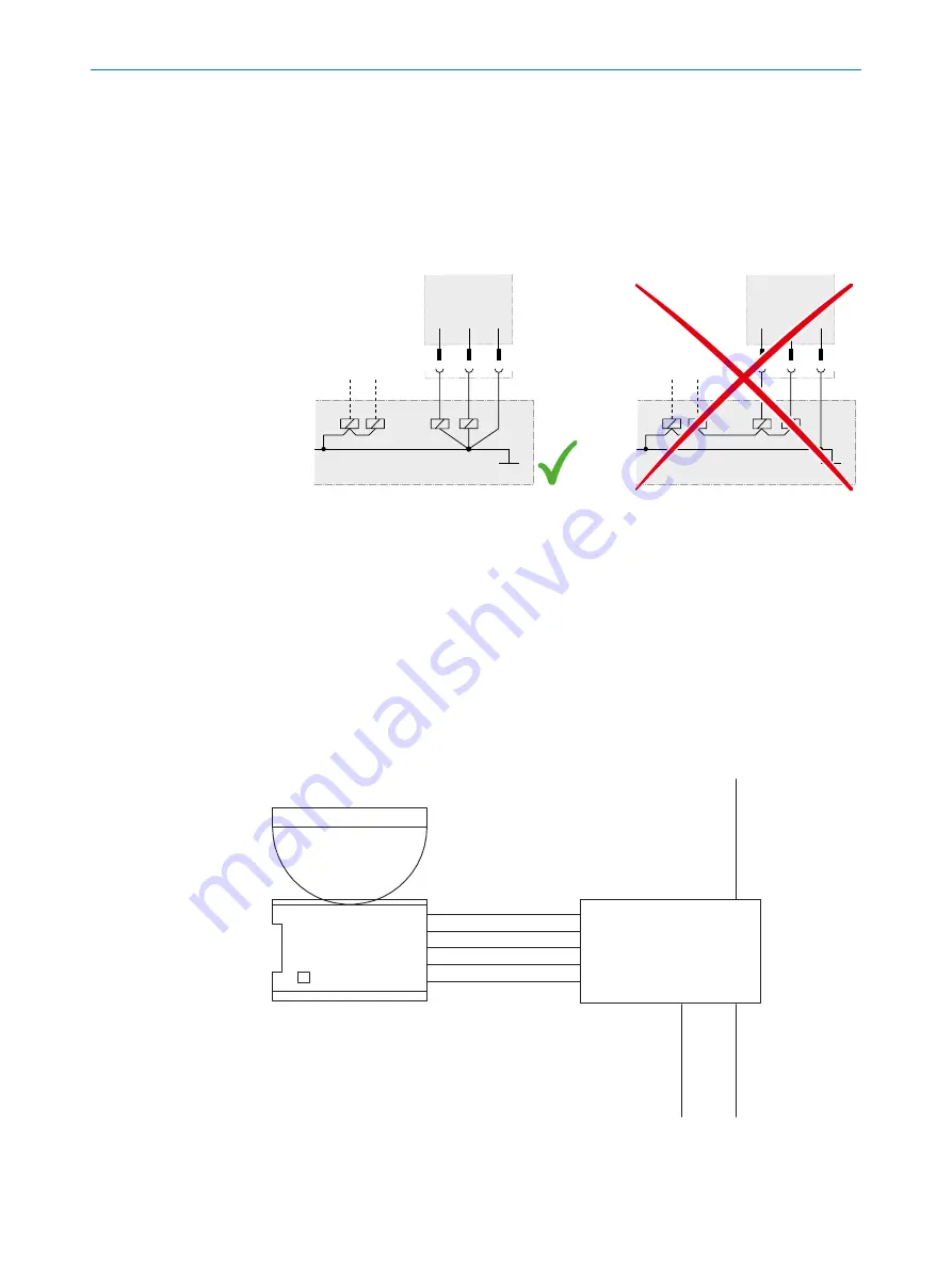
Prevent the formation of a potential difference between the load and the protec‐
tive device. If you connect loads to the OSSDs (safety outputs) that then also
switch if controlled with negative voltage (e.g., electro-mechanical contactor with‐
out reverse polarity protection diode), you must connect the 0 V connections of
these loads and those of the corresponding protective device individually and
directly to the same 0 V terminal strip. In the event of a fault, this is the only way to
ensure that there can be no potential difference between the 0 V connections of
the loads and those of the corresponding protective device.
O
S
SD A
O
S
SD B
O
S
SD A
O
S
SD B
Figure 34: No potential difference between load and protective device
Requirements for the electrical control of the machine
The OSSDs are short-circuit protected to 24 V DC and 0 V. When the protective field is
clear, the OSSDs signal the ON state with the HIGH signal level (non-isolated). If there
are objects in the protective field or there is a device fault, the OSSDs signal the OFF
state with the LOW signal level.
4.4.5
Connection diagrams
FE on the M12 plug connector
The safety laser scanner can be integrated via an AIDA-compliant fieldbus module. In
the example, the functional earth is connected to the M12 plug connector.
microScan3
Core I/O AIDA
+24 V DC
OSSD 1.B
OSSD 1.A
0 V DC
FE
FE
FE
0 V DC
+24 V DC
+24 V DC
+24 V DC
In0
FE
0 V DC
In1
FE
0 V DC
AIDA
Field bus module
Figure 35: Connection diagram with FE on the M12 plug connector
4
PROJECT PLANNING
50
O P E R A T I N G I N S T R U C T I O N S | microScan3 Core I/O AIDA
8017784/1ELL/2022-01-21 | SICK
Subject to change without notice