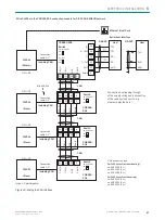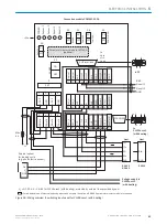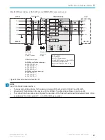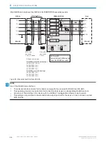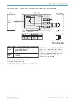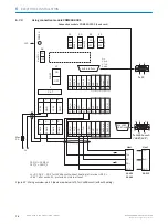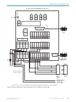
Wire switching outputs “External output 1 and 2” of the CLV69x on the CDB650-204 connection module
Load (e.g. PLC)
GND
Discharge wiring:
apply free running
diode directly to
the load!
In the case of
inductive load:
U
a
Specifications of the switching outputs “External output 1 and 2”
CLV69x
Serial Aux
(RS-232)
CDB650-204
CMC600
U
IN
*
The CLV69x releases the output states of its logical
outputs “External output 1 and 2” via its serial Aux
interface.
Via the connecting cable, the CMC600 automatically
accepts the statuses in a software-controlled manner
and transfers them to its physical outputs “EXT. OUT 1
and 2“ in the CDB650-204.
“External
output 1,
output 2”
Z
Name
22
GND
6
Shield
CDB650-204
CLV69x
Terminal Z
Name
Output
23
24
EXT. OUT 1
EXT. OUT 2
External output 1
External output 2
Functional allocation for switching outputs via
SOPAS-ET configuration software.
Logic
Properties
Electrical
values
PNP switching to supply voltage U
IN
*
(default: no function,
logic: not inverted [active high])
–Short-circuit pro temperature protected
– Not electrically isolated from U
IN
*
0 V ≤ U
a
≤ U
IN
*
Guaranteed:
(U
IN
* −1.5 V) ≤ U
a
≤ U
IN
* in the case of I
a
≤ 100 mA
Figure 54: Wiring switching outputs “External output 1 and 2”
ELECTRICAL INSTALLATION
6
8014396/ZMG8/2017-07-04 | SICK
O P E R A T I N G I N S T R U C T I O N S | CLV69x
61
Subject to change without notice


