- 11 -
3 HARDWARE INSTALLATION
Before removing or installing any of these devices including CPU, DIMMs,
Add-On Cards, Cables, please make sure to unplug the onboard power
connector.
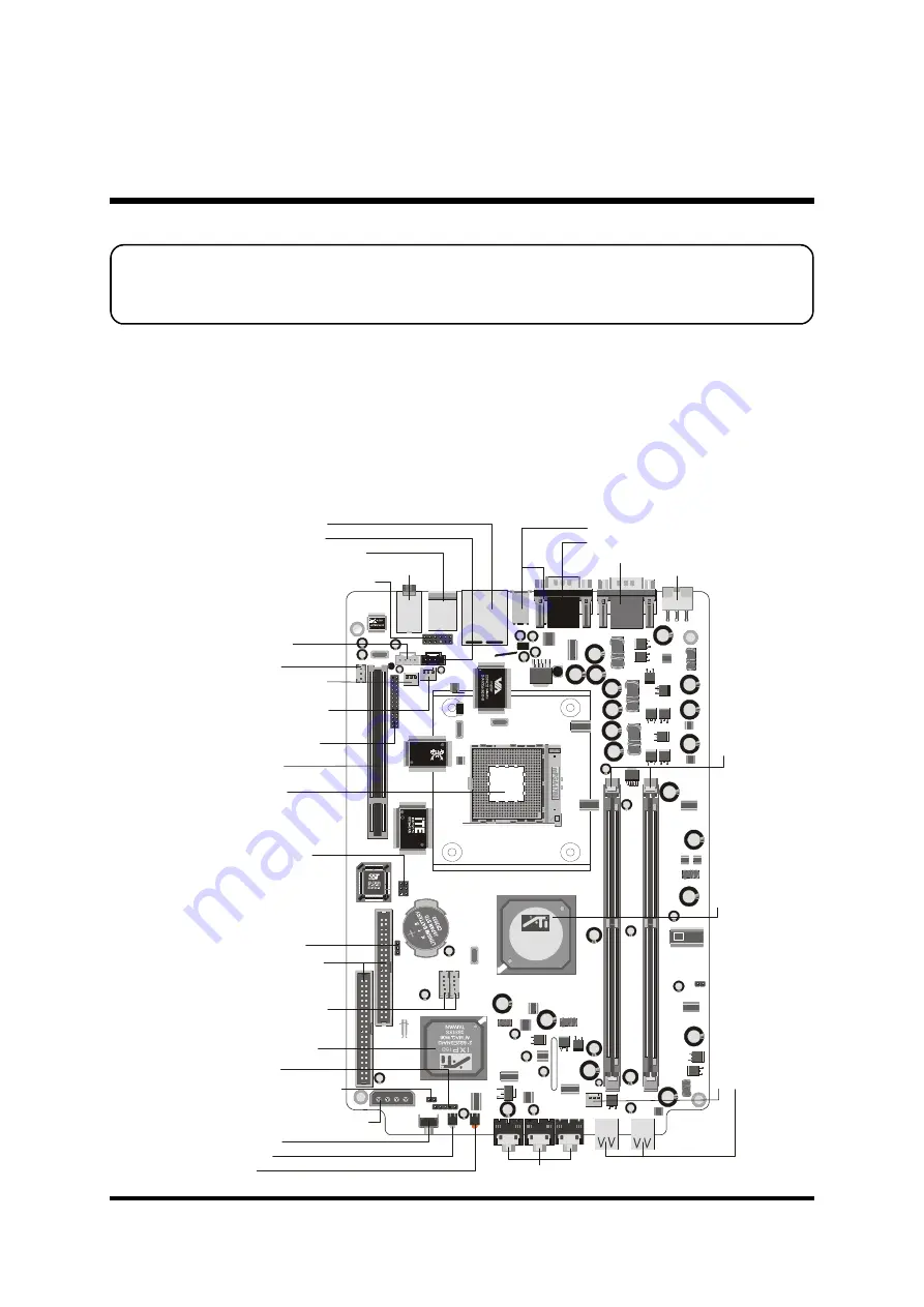
This section outlines how to install and configure your mainboard. Refer to the following
mainboard layout to help you to identify various jumpers, connectors, slots, and ports. Then
follow these steps designed to guide you through a quick and correct installation of your
system.
3.1 Step-by-Step Installation
Accessories Of FT62
JP1
J3
PC
I1
1
ID
E1
ID
E2
FAN2
c A
m
M
e
g
a
8
7
-9
6
M
G
S
K
H
1
FAN3
FAN1
R
aoeon
9100 1GP
215RPS3AGA21H
G45744.1.W11
0330AA
TAIWAN
AU
DIO
1
KB
1
1
J9
J11
1
J6
1
J7
1
J2
1
1
1
J5
RT
L81
00C
3
213
5S
1
311
T
A IW
A N
ATX1
DI
M
M
1
DI
M
M
2
CA331057C
0330 - 014
9P750CF
ICS
SPDIF
J8
US
B0
US
B1
PS/2 Keyboard/Mouse
s
Port
DC-IN Connector
-ATX3
COM & SPDIF-out Ports
IrDA Connector-
J7
One PCI Slot
EXT. PRINT Port-
J6
Clear CMOS-
JP1
Power ON Connector-
J5
Extended USB 2.0
Headers-USB0,USB1
Two IDE Connectors
-
IDE1/IDE2
ATX 12V/5V Connector-
ATX1
Fan Connector-
FAN3
SOCKET 478
Center/Bass/Rear-Out/Front-Out Headers
ATI IXP150 Chipset
LAN & USB 2.0
s
Port
Fan Connector-
FAN1
Wireless KB/MS Connector-
J3
CD_IN Connector-
J9
VGA & Clear CMOS & TV-out Ports
Mic-in/Line-in/Line-out Connectors
Reset Button
Power LED
HD LED
Auxiliary CD-IN
Connector-
J11
SPDIF IN-
J8
Reserved-
J2
F
a
n
C
o
n
n
e
c
to
r
-F
A
N
2
U
S
B
2
.0
C
o
n
n
e
c
to
rs
A
T
I
R
S
3
0
0
C
h
ip
s
e
t
T
w
o
1
8
4
-p
in
D
D
R
-S
D
R
A
M
D
IM
M
S
o
c
k
e
ts
1394a Ports


