background image

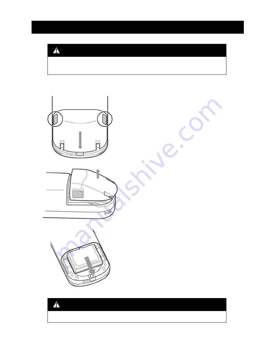
Push the corners of Battery compartment 
cover with your fingers and slide until a gap 
opens at the bottom.

Lift Battery compartment cover to open.

Remove Rechargeable battery.

5. Changing Rechargeable battery (Sensor)

Warning

Never use Rechargeable battery if it is inflated.
It may cause overheating, fire or explosion.

1. Remove Battery compartment cover.

Caution

Turn off the power when removing the 

Battery compartment cover

.

Содержание Handy Skin Sensor II

Страница 1: ...arging Sensor 14 4 Charging Rechargeable battery 15 5 Changing Rechargeable battery Sensor 16 Troubleshooting 18 USB connection with the designated device 21 Specifications 22 This manual contains important information regarding the safe use of this product Read all the safety and operating instructions before operating the product ...

Страница 2: ...ctric shocks Do not leave the unit in places where it may be exposed to high temperatures such as direct sunlight a heat source and flame e g inside a vehicle during summer Doing so may increase the internal temperature and cause explosion or fire Do not use this unit in places where it may be exposed to oil fumes steam high humidity chemicals or dust Water oil grime humidity or dust inside the un...

Страница 3: ... water Do not insert a finger or metal object like a wire into the unit Doing so may cause personal injury and damage to the unit Keep out of the reach of children to prevent injury Do not leave the lens facing directly toward the sun or other source of strong light It may cause fire or damage internal components Do not use this unit inside a vehicle such as an airplane Electromagnetic waves emitt...

Страница 4: ...nnection If the unit has not been used for a long time the battery may lose power through self discharge Change it or charge before use Do not place on an unstable surface Dropping may result in an accident or injury A rapid change in temperature may cause condensation If condensation occurs do not use the unit immediately Wait until it is dry before use Do not use near a cell phone or a microwave...

Страница 5: ...ion or radio frequency identification reader in use nearby 2 If this unit interferes with a radio frequency identification reader immediately stop data transmission and contact Support Center for further instructions Depending on your wireless LAN environment including the structure material of the building obstacles software and signal transmission the speed of the connection will vary Note the c...

Страница 6: ...sposed of in the regular trash as household waste HSSⅡ products are a built in battery type If you are selling them in the E U you are required to provide the product data complying with the revised Directive on Waste Electrical and Electronic Equipment 2012 19 EU Since the internal batteries of HSSⅡ products cannot be replaced when they are disposed of they are collected and disassembled in accor...

Страница 7: ...e equipment into an outlet on a circuit different from that to which the receiver is connected Consult the dealer or an experienced radio TV technician for help Cet équipement a été testé et trouvé conforme aux limites pour un appareil numérique de Classe B conformément à la partie 15 des règles FCC Ces limites sont conçues pour fournir une protection raisonnable contre les interférences nuisibles...

Страница 8: ...ces et 2 cet appareil doit accepter toute interférence y compris les interférences pouvant entraîner un fonctionnement indésirable de l appareil RF exposure compliance This transmitter must not be co located or operating in conjunction with any other antenna or transmitter Cet émetteur ne doit pas être localisé ou fonctionner avec toute autre antenne ou émetteur Caution Any changes or modification...

Страница 9: ...er switch Measurement button Battery compartment cover Strap hole With Battery compartment cover open Close up Serial number It is printed on the inside If you remove Cable hole cover store safely in a packaging box 1 Components Sensor Serial number is printed on Sensor in Battery compartment and on Sensor stand on the back and the back of the skin tone calibration plate Turn off the power when re...

Страница 10: ...ibration plate RGB Value USB connector With Skin tone calibration plate cover open Seen from the top Serial number Battery slot Skin tone calibration plate LED lamp Serial number Close up Serial number and the value shown here are an example 1 Components Sensor stand ...

Страница 11: ...the designated device Use when you connect Sensor to the designated device Contact Support Center before use Insert each battery to Sensor and Sensor stand 1 Components USB cable miscellaneous AC adapter for Sensor stand AC USB adopter USB cable for Sensor with a bushing Rechargeable battery 2 pcs Locking screw Connector stopper Locking screw and Connector stopper are attached to Sensor stand ...

Страница 12: ...or Locking screw Connector stopper 2 Setting up Sensor stand 1 Connect AC adapter for Sensor stand to Sensor stand 2 Loosen Locking screw secure USB connector with Connector stopper and then tighten Locking screw ...

Страница 13: ...sor stand through Cable guide Handle with care and do not damage the cable 4 Place Sensor stand on a flat surface Plug AC adapter into an electrical outlet Caution Only use included AC adopter for Sensor stand Using other AC adopters may result in damage and malfunction of Sensor and Sensor stand ...

Страница 14: ...is placed in a wrong direction or not set in place properly 2 Sensor stand will charge the battery inside Sensor LED lamp indication Charging LED lamp on Sensor turns red Fully charged LED lamp on Sensor turns green Caution If you place Sensor on Sensor stand while it is turned off it will still charge but LED lamp will not turn on ...

Страница 15: ...irection Caution It will not charge if it is inserted in a wrong direction 2 Sensor stand will charge it LED lamp indication Charging LED lamp on Sensor stand turns red Fully charged LED lamp on Sensor stand turns green Caution If Sensor is on Sensor stand at the same time it will charge Sensor but not the inserted Rechargeable battery LED lamp on Sensor stand will blink in green ...

Страница 16: ...ft Battery compartment cover to open Remove Rechargeable battery 5 Changing Rechargeable battery Sensor Warning Never use Rechargeable battery if it is inflated It may cause overheating fire or explosion 1 Remove Battery compartment cover Caution Turn off the power when removing the Battery compartment cover ...

Страница 17: ...nd slotted groove on the left side on the battery Fully insert Rechargeable battery Follow the direction 1 in reverse order and close tightly 5 Changing rechargeable battery Sensor 2 Insert fully charged Rechargeable battery 3 Close Battery compartment cover Caution Assembly which is not specified in this chapter may cause damage or malfunction of the products ...

Страница 18: ...age will appear It stopped working during operation The screen froze Solution Turn it off and turn it back on again If it does not turn off remove Rechargeable battery The screen display does not look right Solution Turn it off and turn it back on again If it does not turn off remove Rechargeable battery The screen is blank the display disappeared Check If the unit is left unused for a while it au...

Страница 19: ...ttery I cannot change the mode with Mode select button Solution Turn it off and turn it back on again If it does not turn off remove Rechargeable battery Mode select button only works on the enlarged shooting screen Sensor is on Sensor stand but it is not charging Check If you are using a power strip is it plugged into an electrical outlet properly Is AC adapter connected to Sensor stand and an el...

Страница 20: ...he serial number refer to p7 8 of this manual LED lamp on Sensor is flashing in red Solution There is a problem with recharging overloaded current overheating Stop use immediately Remove Sensor from Sensor stand and unplug AC adopter from an electrical outlet Contact Support center Sensor stand Symptom Solution LED lamp on Sensor stand is flashing in red Solution There is a problem with recharging...

Страница 21: ... hole cover 3 Connect the correct end of USB cable for Sensor with a bushing As illustrated circle once inside the compartment and securely place the bushing 4 Fully insert Rechargeable battery back in place and close Battery compartment cover Caution Rechargeable battery must be inserted to connect 5 Connect the other end of USB connector to the designated device Caution Turn off the power when r...

Страница 22: ... size 4 0 TFT LCD Resolution 480 800 Displayable colors 260 000 Touch panel Capacitive Wireless LAN Correspondence standards IEEE802 11a b g n 2 4 5GHz Security WEP WPA2 AES Access method Infrastructure Wireless LAN access point 2 4GHz External interface USB Micro B type 2 port microSD Power consumption Approx 2W Power source Lithium ion rechargeable battery Capacity3120mAh Included Battery life W...

Страница 23: ...82 W 62 H 176 D mm AC adopter for Sensor stand Connector ⒶFor an electrical outlet plug ⒷFor sensor Micro B type Length 1 5m Input voltage 100 240V Output voltage 5VDC Output current 1 8A Weight Approx 69g Dimensions Approx 51 W 19 H 48 D mm USB cable For Sensor with a bushing A type Micro B 1m Ⓐ For Sensor Micro B type ⒷFor PC A type Rechargeable battery Lithium ion rechargeable battery Capacity ...

Страница 24: ... Specifications Equipment Name Handy Skin Sensor Ⅱ Model Name HSSⅡ U S A FCC ID 2AO35 HSS2 Canada IC 23766 HSS2 ...

Отзывы: