39(65)
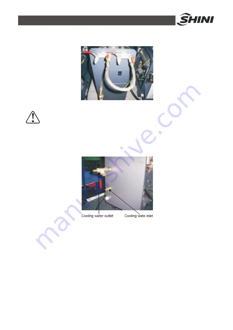
2) Unused mould couplings can be connected with each other by a teflon pipe,
as shown in.
Picture 3-3
:
Mould and Water Couplings 2
Note!
Cooling water inlet and outlet as shown by the Figure. Please do not
connect reversely. Please connect the coolng water outlet with high
temperature resistant pipe when temperature is above 100
℃
.
Picture 3-4
:
Mould and Water Couplings 3
3) Connect cooling water inlet with water supply and cooling water outlet with a
drainage pipe. After that, turn on water supply.
3.3 Power Supply
Make sure that power supply is the same as required before installation.
Mould heater are generally set to be used with 3
Ф
400V power supply or other
specifications according to customers' requirement.
Содержание STM-1220-PW
Страница 1: ...STM PW Series Hi Temp Water Heater Date Dec 2014 Version Ver B English ...
Страница 2: ......
Страница 24: ...24 65 2 3 Electrical Diagram 2 3 1 Main Circuit STM PW 400V Picture 2 5 Main Circuit STM PW 400V ...
Страница 25: ...25 65 2 3 2 Control Circuit STM PW 400V Picture 2 6 Control Circuit STM PW 400V ...
Страница 26: ...26 65 2 3 3 Electrical Components Layout STM PW 400V Picture 2 7 Thermocouple and Terminal Layout STM PW 400V ...
Страница 29: ...29 65 2 3 5 Main Circuit STM PW 230V Picture 2 8 Main Circuit STM PW 230V ...
Страница 30: ...30 65 2 3 6 Control Circuit STM PW 230V Picture 2 9 Control Circuit STM PW 230V ...
Страница 31: ...31 65 2 3 7 Electrical Components Layout STM PW 230V Picture 2 10 Electrical Components Layout STM PW 230V ...
Страница 62: ...62 65 ...


