background image


43(61) 


3.6  Combined Installation of Modules 

1) Disassembly the sideplates around the machine, calibrate the cooling water 

inlet to combine the modules. Use rubber soft pipe to connect the module's 
chilling water pipe. 

2) The non-exist end of the cooling water pipe should be fixed by flange. 
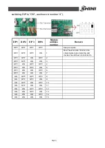
3) Refers to wiring diagram to tandem the communication line to next 

submodule, the communication line of which tandems to next submodule 
thereby.   


Picture 3-6

Combined Installation of Modules 

3.7  Essentials for Electric Wiring 

1) The electricity supply should use special branch circuit. 
2) Wiring work should be conducted according to relevant national electric 

standards and grounding. 

3) Refer to wiring diagram to conduct wiring work. Lock up every contact screws, 

do not let them loosen. 

4) The voltage has to be stable when in operation, take all the voltage down fall 

into consideration, the unit working voltage should maintain at

±

10% within 

rated voltage. Over high or over low voltage will bring bad effect to the unit. 

5) The length of the power cable must ensure the voltage gap value between 

the head and tail of cable be less than 

±

2% within rated voltage, if the length 

can not be shorter. Then enlarge the diameter of the cable. 

Содержание SICC-120A

Страница 1: ...SICC A Series Air cooled Central Water Chiller Date Apr 2013 Version Ver B English...

Страница 2: ......

Страница 3: ...g Principle 23 2 1 2 Working Flow Instruction 23 2 2 Electrical Diagram 24 2 2 1 Main Circuit SICC 60A 24 2 2 2 Control Circuit SICC 60A 25 2 2 3 Electrical Components Layout SICC 60A 26 2 2 4 Electri...

Страница 4: ...rface of System Function 46 4 4 1 Interface Demonstration 47 4 4 2 Interface Operation 47 4 5 System Parameter Setup Interface 47 4 5 1 Interface Demonstration 47 4 5 2 Interface Operation 47 4 6 Inqu...

Страница 5: ...13 2 Interface Instruction 53 4 14The Configuration of Module Unit 53 5 Trouble shooting 57 6 Maintenance and Repair 58 6 1 Daily Repair and Check Items 59 6 2 Monthly Periodical Checking Items 59 6 3...

Страница 6: ...C 60A 25 Picture 2 4 Electrical Components Layout SICC 60A 26 Picture 2 5 Main Circuit SICC 90A 28 Picture 2 6 Control Circuit SICC 90A 29 Picture 2 7 Electrical Components Layout SICC 90A 30 Picture...

Страница 7: ...on 48 Picture 4 8 System Configuration 48 Picture 4 9 Unit Running Settings 50 Picture 4 10 Parameter Setting 50 Picture 4 11 Unit Running Setup 1 51 Picture 4 12 Unit Running Setup 2 51 Picture 4 13...

Страница 8: ...8 61...

Страница 9: ...e machine or personal injuries SICC A series are applicable for cooling moulds to reduce products molding cycle also they are available in the cooling of equipments in order to maintain a normal tempe...

Страница 10: ...tube for each module alone The soft rubber tube is used to connect the modules thus it is very convenient to construct Adopts imported components like scroll compressor expansion valve which ensure s...

Страница 11: ...Any modifications of the machine must be approved by SHINI in order to avoid personal injury and damage to machine We shall not be liable for any damage caused by unauthorized change of the machine Ou...

Страница 12: ...12 61 1 3 Technical Specifications 1 3 1 SICC A Series Outline Dimensions Picture 1 1 Series Outline Dimensions SICC 60A...

Страница 13: ...13 61 Picture 1 2 Series Outline Dimensions SICC 90A...

Страница 14: ...14 61 Picture 1 3 Series Outline Dimensions SICC 120A...

Страница 15: ...15 61 1 3 2 The Illustrative Drawing of SICC A Modules Grouping Picture 1 4 The Illustrative Drawing of SICC A Modules Grouping...

Страница 16: ...16 61 Picture 1 5 SICC 60A Refrigerating Performance Curves...

Страница 17: ...17 61 Picture 1 6 SICC 90A Refrigerating Performance Curves...

Страница 18: ...18 61 Picture 1 7 SICC 120A Refrigerating Performance Curves...

Страница 19: ...0 60Hz Total Power Running Current Startup Current Hermetic Scroll Closed Shell and Tube Evaporator Tube fin Air cooled Condenser Refrigeration Capacity Power Compressor Refrigerant Evaporator Condens...

Страница 20: ...conditioner is designed for adults Keep children away from it 9 Any deeds trying to change its specification are dangerous 10 Don t use evaporable solvents oil or toluene to avoid accidents 11 Ensure...

Страница 21: ...ul this symbol stands that take careful hereby Attention No need for regular inspection because all the electrical parts in the control unit are fixed tightly 1 4 3 Signs and Labels This is for indica...

Страница 22: ...man made installations operation and maintenances upon machines without referring to the Manual prior to machine using 2 Any incidents beyond human reasonable controls which include man made vicious o...

Страница 23: ...fall comes into shell and tube type evaporator The low temp low pressure and satuated refrigerant absorbs the heat from cooling water so to low down its temp The state of the shell and tube type evapo...

Страница 24: ...24 61 2 2 Electrical Diagram 2 2 1 Main Circuit SICC 60A Picture 2 2 Main Circuit SICC 60A...

Страница 25: ...25 61 2 2 2 Control Circuit SICC 60A Picture 2 3 Control Circuit SICC 60A...

Страница 26: ...26 61 2 2 3 Electrical Components Layout SICC 60A Picture 2 4 Electrical Components Layout SICC 60A...

Страница 27: ...18 30 500V YE46002000100 13 F12 Fuse 2A YE41001000000 14 PCB Control board 230VAC 50 60Hz M 02 15 HMI Hmi 230VAC 50 60Hz M 02 16 X1 Terminal board 660V 112A YE61103500000 17 X2 Terminal board 660V 41...

Страница 28: ...28 61 2 2 5 Main Circuit SICC 90A Picture 2 5 Main Circuit SICC 90A...

Страница 29: ...29 61 2 2 6 Control Circuit SICC 90A Picture 2 6 Control Circuit SICC 90A...

Страница 30: ...30 61 2 2 7 Electrical Components Layout SICC 90A Picture 2 7 Electrical Components Layout SICC 90A...

Страница 31: ...8 30 500V YE46002000100 13 F12 Fuse 2A YE41001000000 14 PCB Control board 230VAC 50 60Hz M 02 15 HMI Hmi 230VAC 50 60Hz M 02 16 X1 Terminal board 660V 112A YE61163500000 17 X2 Terminal board 660V 41A...

Страница 32: ...32 61 2 2 9 Main Circuit SICC 120A Picture 2 8 Main Circuit 1 SICC 120A...

Страница 33: ...33 61 Picture 2 9 Main Circuit 2 SICC 120A...

Страница 34: ...34 61 2 2 10 Control Circuit SICC 120A Picture 2 10 Control Circuit SICC 120A...

Страница 35: ...35 61 2 2 11 Electrical Components Layout SICC 120A Picture 2 11 Electrical Components Layout SICC 120A...

Страница 36: ...500V 32A 2P YE41032200000 12 Fuse 2A 18 30 500V YE46002000100 13 F12 Fuse 2A YE41001000000 14 PCB Control board 230VAC 50 60Hz M 02 15 HMI Hmi 230VAC 50 60Hz M 02 16 X1 Terminal board 660V 41A YE6116...

Страница 37: ...cording to local regulations 3 Use independent electricity wire and power switch The diameter of the wire should not be less than that of electric cabinet s wire 4 The end of the electricity wire shou...

Страница 38: ...e existence nearby to acoid efficiency reduction due to absorbing hot air 2 No impact imposed by high temperature vapor or oil stain 3 Avoid being spattered by water vapor when choosing installation s...

Страница 39: ...t operation and prevent the vibration and noise transmission from interfering the under floors the absorber should be laid between the unit base and base platform Please maintain horizontal when insta...

Страница 40: ...m finally 2 If the large scale machine cannot be decomposed then dig hole in the wall or earth to transport it Path adjustment Adjust with the wall floor to facilitate transporting Others Arrangenent...

Страница 41: ...ank should be placed higher by at least 1m than top of the whole set of water distribution pipelines to buffer the water volume s expansion or contraction and the isolated backup water pressure to wat...

Страница 42: ...e meter 6 Thermometer 7 Flowmeter 8 Solenoid valve 9 Rubber soft pipe Picture 3 4 Same Direction Way 1 Names of Parts 1 Stop valve 2 One Way valve 3 Y type Filtration valve 4 Pump 5 Pressure meter 6 T...

Страница 43: ...iring 1 The electricity supply should use special branch circuit 2 Wiring work should be conducted according to relevant national electric standards and grounding 3 Refer to wiring diagram to conduct...

Страница 44: ...owed in the following photo 8 Inorder to ensure personal safety to avoid electric shock due to creepage the housing of the unit needs to have a good grounding protective device to avoid electric shock...

Страница 45: ...electing interface d 1 Time setup interface 1 Set system time 2 Set auto start stop time e System parameters setup interface 1 System configuration 2 Tthe setup for unit running 3 The setup of system...

Страница 46: ...46 61 Picture 4 2 Interfaces Show 4 3 Main Working Interface 4 3 1 Interface Demonstration Picture 4 3 Main Working Interface 4 4 Selecting Interface of System Function...

Страница 47: ...back to main working interface 4 5 System Parameter Setup Interface 4 5 1 Interface Demonstration Picture 4 5 System Parameter Setup Interface 4 5 2 Interface Operation Press or key to select differe...

Страница 48: ...k to time setting interface 4 8 System Configuration 4 8 1 Interface Demonstration Picture 4 8 System Configuration 4 8 2 Interface Instruction To set up the parameters for system configuration 1 Modu...

Страница 49: ...onnection Note There is no heating function for this machine 6 Module number select the module that needs online function 7 Setup online function check to see if it needs to be online When displays st...

Страница 50: ...back to the time setting interface 4 10 Parameter Setting 4 10 1 Interface Demonstration Picture 4 10 Parameter Setting 4 10 2 Interface Operation Press or key to select different functions press or...

Страница 51: ...module firstly then press menu key to access into every module s running status parameters As enterring into interface demonstration 2 3 It displays the inquired module number firstly then folllowing...

Страница 52: ...number the rest displays the elated temp Value from module testing 4 12 3 Interface Operation Press or key to select different module module number is in the range of network module number press retur...

Страница 53: ...ts instruction please refer to function instruction book 4 14 The Configuration of Module Unit Shini SICC A series adopt modular design with three unit modules including SICC 60A SICC 90A and SICC 120...

Страница 54: ...rts and they are conveniently to purchase 2 Control Line Connection of Host Sub Modules Complete control line connection following chilled water pipeline connection No 1 terminal in host PCB connects...

Страница 55: ...F OFF ON 1 Must have module 1 which the shared water pipe detecting and devices has all been connected to OFF OFF ON OFF 2 OFF OFF ON ON 3 OFF ON OFF OFF 4 OFF ON OFF ON 5 OFF ON ON OFF 6 OFF ON ON ON...

Страница 56: ...FF single cool 4 Auxiliary heat 1 indicate whether 1 module is equipped with auxiliary heat ON means connecting one and OFF no connecting 5 Auxiliary heat 2 indicate whether 2 module is equipped with...

Страница 57: ...Check and reset 4 Edit the value for heat flow 5 Check and reset Compressor stops immediately after it starts 1 Air inlet or outlet gets hindered 2 Condenser is dirty 3 Bad ventilation due to bad lan...

Страница 58: ...upply unless emergncyoccurs 2 When failure occurs and machine stops press the main power switch alarm light will go out Check the failure and do not start the machine before trouble shooting 3 Check t...

Страница 59: ...ng Items 1 Check if the screws loosen 2 Clean indoor air conditioner box or filter of cool air blower 3 Check if the joint of the pipelines leaks 4 Check the wire to see if there is any damage the con...

Страница 60: ...hes Check all wires of the machine Check whether pressure gauges are accurate Check whether compressor temperature is normal Check whether cooling water circulation is normal 6 4 4 Weekly Check Check...

Страница 61: ...yearly Check and clean filter and expansion valve Check the whole machine condition Clean condenser 6 4 8 Yearly Checking Check whether the contactor is normal 6 4 9 3 year Checking PC board renewal N...

Отзывы: