54(61)
In modularized configuration for chilled water circuit, there are two methods of
connection: reversed return and direct return. In reversed return connection
chilled water flow distance through every unit module is the same while in direct
return the flow distance is not equal. Flow distance in reversed return has the
same resistance and water flow while flow distance in direct return has the
different resistance and water flow. Generally, chilled water pipeline connection
adopts reversed return type.
Chilled water inlet and outlet in SICC-A unit module adopt 5 inch flange as joint
face. Use 5 inch rubber connecting flange can complete the combination of two
unit modules of pipeline. Both flange and rubber connecting flange are national
standard parts and they are conveniently to purchase.
2) Control Line Connection of Host/Sub Modules
Complete control line connection following chilled water pipeline connection.
No.1 terminal in host PCB connects display control panel. No.2 terminal
connects No.1 terminal of sub 1# module and No.2 terminal of sub 1#module
connects No.1 terminal of sub 2# module. Complete connection in sequence as
number of unit module increases. (Note: four lines in No.1 terminal and three in
No.2. When connecting No.1 and No.2, the black line in No.1 terminal is free of
connection).
3) Control Setting
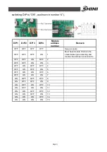
Complete control setting following control line connection. Firstly is the setting of
each unit module address, which can be finished by controlling DIP switches on
PCB. Address range is from 1 to 15. On the using of module combination,
display control panel connects 1# module to centrally control all unit modules in
the system. Refer picture below for DIP switch setting (Black area indicates
Содержание SICC-120A
Страница 1: ...SICC A Series Air cooled Central Water Chiller Date Apr 2013 Version Ver B English...
Страница 2: ......
Страница 8: ...8 61...
Страница 13: ...13 61 Picture 1 2 Series Outline Dimensions SICC 90A...
Страница 14: ...14 61 Picture 1 3 Series Outline Dimensions SICC 120A...
Страница 16: ...16 61 Picture 1 5 SICC 60A Refrigerating Performance Curves...
Страница 17: ...17 61 Picture 1 6 SICC 90A Refrigerating Performance Curves...
Страница 18: ...18 61 Picture 1 7 SICC 120A Refrigerating Performance Curves...
Страница 24: ...24 61 2 2 Electrical Diagram 2 2 1 Main Circuit SICC 60A Picture 2 2 Main Circuit SICC 60A...
Страница 25: ...25 61 2 2 2 Control Circuit SICC 60A Picture 2 3 Control Circuit SICC 60A...
Страница 26: ...26 61 2 2 3 Electrical Components Layout SICC 60A Picture 2 4 Electrical Components Layout SICC 60A...
Страница 28: ...28 61 2 2 5 Main Circuit SICC 90A Picture 2 5 Main Circuit SICC 90A...
Страница 29: ...29 61 2 2 6 Control Circuit SICC 90A Picture 2 6 Control Circuit SICC 90A...
Страница 30: ...30 61 2 2 7 Electrical Components Layout SICC 90A Picture 2 7 Electrical Components Layout SICC 90A...
Страница 32: ...32 61 2 2 9 Main Circuit SICC 120A Picture 2 8 Main Circuit 1 SICC 120A...
Страница 33: ...33 61 Picture 2 9 Main Circuit 2 SICC 120A...
Страница 34: ...34 61 2 2 10 Control Circuit SICC 120A Picture 2 10 Control Circuit SICC 120A...
Страница 35: ...35 61 2 2 11 Electrical Components Layout SICC 120A Picture 2 11 Electrical Components Layout SICC 120A...


