ShinewayTech DPM-50 Скачать руководство пользователя страница 37

DPM-50  RF  In  Line  Digital  Power  Meter  User's  Manual 


Shineway Technologies, Inc.  


- 37 -


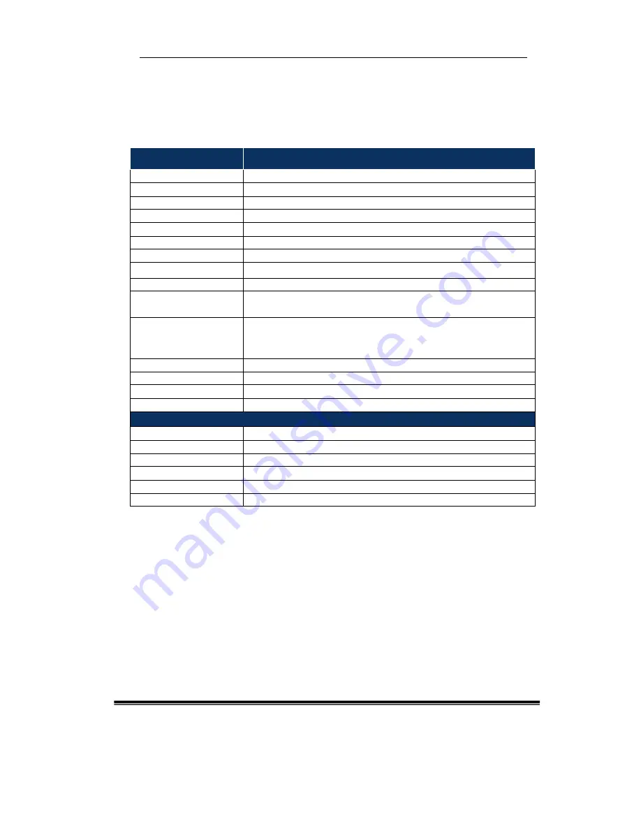
4. Specification 

Model 

DPM-50AP 

Frequency Range 

300-4200MHz 

Average Power Range 

100mW-200W 

Peak Power Range 

100mW-500W 

Dynamic Range (dB) 

≥33 

Insertion Loss (dB) 


≤0.1 

VSWR 

      1.05-99.9 

Crest Factor 

    0 ~ 12dB 

CCDF 

0.1

%

 ~ 100

%


Directivity 

≥30 (<3GHz); ≥28 (>3GHz) 

Average Power 
Measurement Accuracy 

±4%+0.05W (0

~+15

 or +35

~+50

 increase 3%) 

Peak Power 

Measurement Uncertainty   

Pulse Width > 200 µs: ±7% 
1 µs < Pulse Width < 200 µs: ±10% 
Pulse Width < 1 µs: ±15%   
Pulse Width < 0.5 µs: ±20% 

Impedance 


50Ω 

Connector 

      N (Female) 

Data Interface 

          USB 

DPM Interface 

                                                            DB9   

General Specifications


Power Supply (Monitor) 

NiMH Battery/ AC Adaptor


Operating Temperature 

-10

 ~ 50


Storage Temperature 

-20

 ~ 70


Relative Humidity 

0~85% 

(Non-condensing)


Weight 

480g (Sensor)/ 900g (MONITOR)   

Dimensions (H×W×T) 

130×(95)×124×34mm (Sensor); 220×110×70mm (MONITOR) 

* Specifications subject to change w ithout notice  

Содержание DPM-50

Страница 1: ...DPM 50 RF In Line Digital Power Meter User s Manual...

Страница 2: ...DPM 50 RF In Line Digital Power Meter User s Manual Shineway Technologies Inc 2 Shineway Technologies Inc...

Страница 3: ...procedure or the like which if not correctly performed or adhered to could result in damage to or destruction of part or the entire product Do not proceed beyond a CAUTION sign until the indicated co...

Страница 4: ...DPM 50 RF In Line Digital Power Meter User s Manual Shineway Technologies Inc iv Connection avoid the reverse connection to the device although it is designed with reverse polarity protection...

Страница 5: ...ion vii 1 3 Introduction viii 2 Operation 9 2 1 Sensor Interfaces 9 2 2 RF Digital Power Meter Software 10 2 2 1 Driver Installation 11 2 2 2 Menu 19 2 3 Measurement Operation 34 2 3 1 Connection 34 2...

Страница 6: ...DPM 50 RF In Line Digital Power Meter User s Manual Shineway Technologies Inc vi 5 3 Warranty Registration 39 5 4 Returning Instruments 39 5 5 Contacting Customer Service 40...

Страница 7: ...cal electrical and optical inspection prior to shipment For detailed packing information please refer to the packing list Upon receiving the instrument please check for any obvious signs of physical d...

Страница 8: ...tenna system and saves test data for analysis and evaluation The typical application is to monitor the transmitter and antenna of wireless base station during network installation and maintenance DPM...

Страница 9: ...ion This part introduces the basic operation of ShinewayTech DPM 50 Please read this manual carefully for optimal operation Should you encounter any problems during operation you are welcome to contac...

Страница 10: ...Digital Power Meter Software The software is for controlling DPM 50 on PC to measure power display save and print the result Function 1 USB device detection and communication 2 Select frequency to be...

Страница 11: ...continuously Run Continues Continuous measurement result is displayed in curve chart 9 Gauge and curve chart range setting 10 Indication of outranged measurement data by color sound dialogue window 11...

Страница 12: ...DPM 50 RF In Line Digital Power Meter User s Manual Shineway Technologies Inc 12 Select Install from a list or specific location Advanced click Next...

Страница 13: ...DPM 50 RF In Line Digital Power Meter User s Manual Shineway Technologies Inc 13 Select the path of driver click Next...

Страница 14: ...DPM 50 RF In Line Digital Power Meter User s Manual Shineway Technologies Inc 14 Click Finish to close the wizard And then the PC will find a new device again...

Страница 15: ...DPM 50 RF In Line Digital Power Meter User s Manual Shineway Technologies Inc 15 Select Install from a list or specific location Advanced click Next...

Страница 16: ...DPM 50 RF In Line Digital Power Meter User s Manual Shineway Technologies Inc 16 Select the path of driver click Next...

Страница 17: ...0 RF In Line Digital Power Meter User s Manual Shineway Technologies Inc 17 Click Finish to close the wizard Right click My Computer on the desktop select Properties click Manage label click Device Ma...

Страница 18: ...DPM 50 RF In Line Digital Power Meter User s Manual Shineway Technologies Inc 18...

Страница 19: ...r Meter USB Device appears in the list the driver is installed otherwise please disconnect the sensor from PC reconnect and install the driver again 2 2 2 Menu After driver is installed run the RF Dig...

Страница 20: ...s Manual Shineway Technologies Inc 20 2 Tool bar 3 Information bar 4 Result display area 5 Property bar 1 Menu bar Top Menu Files menu Files menu includes Open File Save File Print Preview Print and E...

Страница 21: ...n Line Digital Power Meter User s Manual Shineway Technologies Inc 21 Open File Click Save Files to save file Input the file name Default DataFile csv the file format is CSV which can be opened with O...

Страница 22: ...DPM 50 RF In Line Digital Power Meter User s Manual Shineway Technologies Inc 22 Save File Click Print Preview to preview the report and data to be printed...

Страница 23: ...DPM 50 RF In Line Digital Power Meter User s Manual Shineway Technologies Inc 23 Print Preview Click Print to configure printer settings and print data Print Click Exit to exit the software...

Страница 24: ...Manual Shineway Technologies Inc 24 Device Info Menu Click Device Info and the menu will roll up and down to check device information Settings menu Settings menu includes Select Frequency Options Cli...

Страница 25: ...In Line Digital Power Meter User s Manual Shineway Technologies Inc 25 Select Frequency roll down Select Frequency while roll up Click Settings menu to input select the settings Test Item submenu unde...

Страница 26: ...If selecting this item there will be a popup window when the measurement exceeds the setting range greater than Max or less than Min If not selecting this item there will not be a popup window what e...

Страница 27: ...enu under Setting Operator Sample Type Sample S N will be shown in the printing report Interval indicates the interval time between two consecutive measurements under continuous measurement mode The m...

Страница 28: ...span Modulation Type 150us CW Burst b w 300us Voice Band AM FM Phase Modulation 15us CW Burst b w 30us Voice Band AM FM Phase Modulation 1 0us CW Burst b w 2us GSM 50kHz AM DQPSK 1 4 symbol rate 24k s...

Страница 29: ...o run a measurement The measurement result will be displayed in the GUI by two ways number and dial The number will be red while it is out of the setting range and be green while it is within the sett...

Страница 30: ...o run a measurement The interval and last time value can be set in the Setting menu The measurement result will be displayed in the GUI by two ways number and dial The number will be red while it is o...

Страница 31: ...B device information if the USB device does not access the computer then the information will be Frequency The user can set the desired frequency There are two ways pre defined frequency and user sett...

Страница 32: ...t by users If the input value exceeds the acceptable range the system will show an error pop up window CCDF Set the threshold value and display the real time CCDF value Click set button a dialog windo...

Страница 33: ...gital Power Meter User s Manual Shineway Technologies Inc 33 CCDF Display Area 5 Result Display Area Result Display Area Measurement results are shown with the trace under continuous measurement mode...

Страница 34: ...ng 1 Mouse position at the coordinates of historical trace 2 Count of successes and failures of measurements 3 USB device access status to computer 4 Device temperature 2 3 Measurement Operation 2 3 1...

Страница 35: ...requency setting frequency method For selecting a common used frequency band click the select frequency drop down menu below select the frequency For user define frequency input the value in the blank...

Страница 36: ...mp cloth to clean the external case do not clean inside Device should be repaired d by qualified technician while damaged Sensor N connector should be put on protective cover to prevent damage when no...

Страница 37: ...ement Accuracy 4 0 05W 0 15 or 35 50 increase 3 Peak Power Measurement Uncertainty Pulse Width 200 s 7 1 s Pulse Width 200 s 10 Pulse Width 1 s 15 Pulse Width 0 5 s 20 Impedance 50 Connector N Female...

Страница 38: ...riod would be repaired or replaced by Shineway Technologies Inc free of charge In no case will Shineway Technologies Inc liabilities exceed the original purchase price of the product 5 2 Exclusions Th...

Страница 39: ...Authorization number And describe briefly reasons for the return of the equipment to allow us offer you more efficient service To return the instrument in the case of repair calibration or other main...

Страница 40: ...on information If you need technical or sales support please contact local Shineway Technologies Customer Service Shineway Technologies China Inc Address Fl 7 Zhongtai Plaza No 3 Shuangqing Rd Haidian...

Отзывы: