


ǦͳͲǦ
ͶǦͶǤ
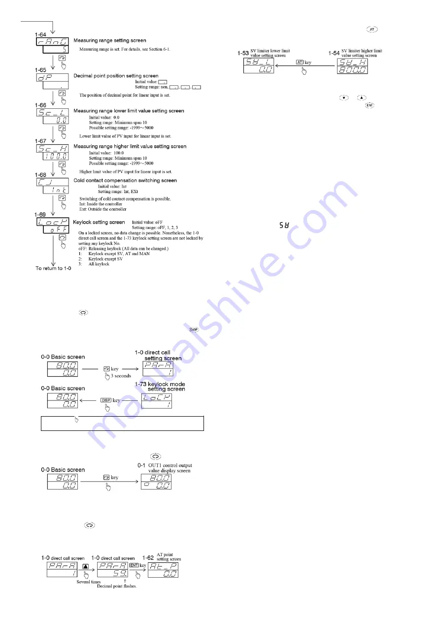
(1) Moving between mode 0 screen group and mode 1 screen
group
ವ
Pressing the
key continuously for 3 seconds on the basic
screen of the mode 0 screen group brings the direct call screen
of the mode 1 screen group onto display. Pressing the
key
on any screen of the mode 1 screen group, the display returns
to the basic screen of the mode 0 screen group.
NOTE:
The mark shown above means pressing the key above
the mark. This applies to all the subsequent drawings.
(2) Moving from screen to screen in the mode 0 screen group
ವ
The next screen appears every time the
key is pressed.
(3) Moving from screen to screen in the mode 1 screen group
ವ
There are three methods of moving from screen to screen in
the mode 1 screen group as shown below:
i) To press the
key in the same way as in the mode 0
screen group. (See (2) above.)
ii) To enter the number of a screen you want to call on the 1-0
direct call screen.
iii) The preceding screen appears every time the
key is
pressed. (This function of AT key works only in the mode 1
screen group.)
ͶǦͷǤ
To change data on each screen, press the
or
key.
Changed data should be registered by pressing the
key.
Once the data is registered, the decimal point on the bottom right
stops flashing and goes out.
ͶǦǤ
(1) 0-5 set value bias setting screen
By setting a bias value for a target set value beforehand,
the
original target set value added with the bias value becomes the
new target value when the DI assigned for SB turns ON
(shorted).
DI ON = Target set value (SV) + bias value (SB)
DI OFF = Target set value (SV)
NOTE: To use the set value bias function, you have to assign
SB to a DI and set SB for SV mode.
(2) 1-16 DI1 setting screen and 1-17 DI2 setting screen
•
If you select [
], SV2 takes effect when DI input turns ON.
•
When to detect external control input signal:
Level input: The action is maintained as long as the contact
remains ON.
Edge input: The action is maintained even when the contact is
turned OFF after it has been in action for 0.3
seconds or longer. If the contact remains ON for
0.3 seconds subsequently, the action is released.
•
If an action of the same type is assigned to DI1 and DI2, the
assignment to DI2 becomes void.
•
An action assigned to a DI cannot be controlled by key
operation. (Priority is given to DI input.)
•
An action through DI input is held even after release of the
DI assignment.
(3) 1-24 remote switching point setting screen
Setting a remote switching point on this screen allows local SV
to be switched to remote SV at the time when remote input
reaches the desired value (%).
•
When oFF is set for remote switching point
Conventional remote switching action
By switching to remote on the remote switching setting
screen (rEm) of the user setting screen group, local is
immediately switched to remote and the remote lamp lights.
•
When a value, i.e., not
“
oFF
”
, is set for remote switching
point
ї
remote switching action according to applied voltage
or current.
In case the value of voltage or current input remotely upon
switching to remote on the remote switching setting screen
(rEm) exceeds the set value (%) of remote switching point,
SV is switched to remote and remote lamp lights. If remote
input falls below the set value (%) of remote switching point,
it switches to local SV and the remote lamp flashes.
Note: There is no remote switching while AT is in execution.
Note: If the remote input at the time when remote switching is set
on the remote switching setting screen (rEm) is below the set
value (%) of remote switching point, the remote lamp flashes
and it is switched to local SV.
digit
digit, Maximum span 5000digit
digit
digit, Maximum span 5000digit
digit
Содержание SR80 Series
Страница 6: ...digit digit digit digit digit digit...
Страница 8: ...digit digit It is conditional that rE_L rE_H It is conditional that rE_L rE_H...
Страница 9: ......


