11
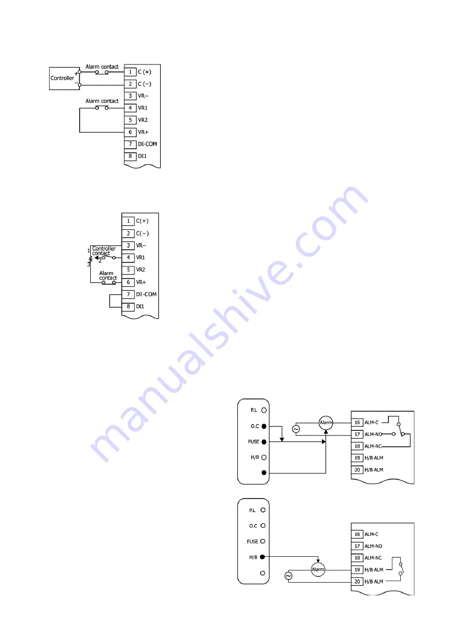
7-3-5 Over-rise protection circuit (for voltage/current input type)
This is a method of cutting off signals from the controller to stop control output.
Cutting off the continuity between terminals 4 (VR1) and 6 (VR+) also causes the output to stop.
7-3-6 Over-rise protection circuit (for contact input type)
In the following wiring diagram, an alarm contact is added to terminal 6 (VR+) to cause the circuit to open, to stop output when the over-rise
prevention becomes active.
The same effect is produced when the contact is connected in series to the contact output of the controller.
7-4. Wiring of alarm circuit
When an over-current alarm, rapid fuse break alarm, or temperature abnormal alarm occurs, continuity is established between terminals 16
(ALM-C) and 17 (ALM-NO), while the path between terminals 16 (ALM-C) and 18 (ALM-NC) is opened. If an alarm occurs, check the monitor
lamps to identify the type of alarm it is.
When a heater break alarm occurs, continuity is established between terminals 19 (H/B ALM) and 20 (H/B ALM), and the monitor lamp (H/B)
lights.
7-4-1 Over-current alarm circuit
If an over-current alarm is detected, output is cut off and the
monitor lamp (O.C.) lights up.
The instrument cuts off output at about 110% of the rated
current.
7-4-2 Rapid fuse blown alarm (option)
If a rapid fuse
blown
alarm is detected, output is cut off and the
monitor lamp (FUSE) lights up.
7-4-3 Internal temperature abnormal alarm
If an internal temperature abnormal alarm is detected, output is
cut off and the monitor lamp (O.H.) lights up.
7-4-4 Heater break alarm
If a heater break alarm is detected, continuity is established
between the H/B ALM terminals, and the monitor lamp (H/B)
lights up.
In this case, the instrument maintains output.
O.H
.
O.H
.


