background image


10 

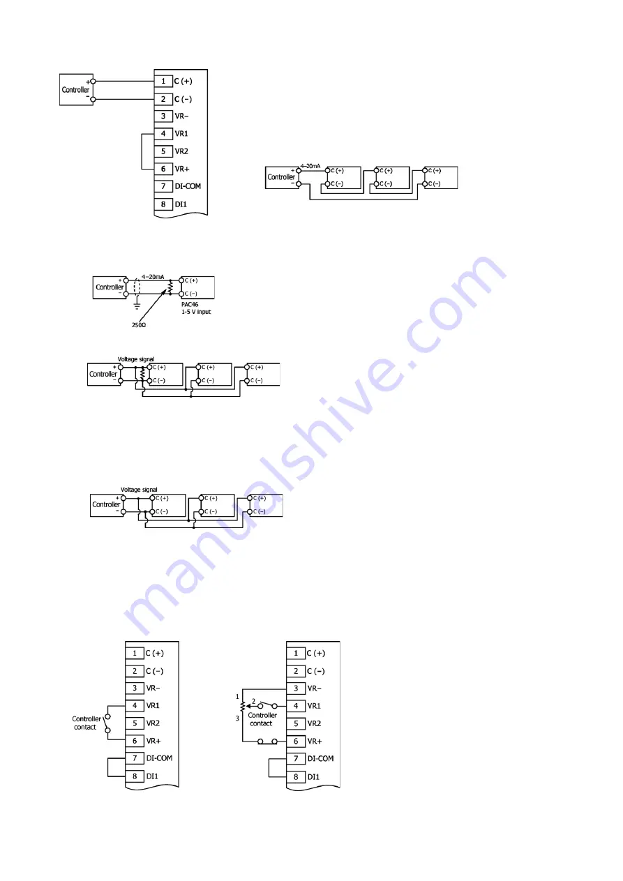
7-3-1 Connection between 4

20 mA output type controller and instrument (4

20 mA input) 


To connect multiple units of the instrument, wire them in series as shown below.


The input resistance of the instrument (4–20 mA input) is 100 Ω. Therefore, if the 
allowable load resistance range of the controller is 600 Ω, up to six units of the 
instrument can be connected.


7-3-2 Connection between 4

20 mA output type controller and instrument (1

5 V input) 

When connecting a 4–20 mA output type controller and the instrument (1–5 V input), connect a 250 Ω resistor to the input terminals in 
parallel.


To connect multiple units of the instrument, wire them in parallel as shown below.


7-3-3 Connection between 0-10 V output type controller and instrument (0-10 V input) 

For this connection, also use the 0-10 V input type instrument.


As the input resistance is high, use two-core shielded cable and prevent the effects of noise by single earthing.


Connect the (+) and (-) terminals of the controller respectively to the input terminals, C (+) and C (-), of the instrument.


To connect multiple units of the instrument, connect them in parallel as shown below. However, resistor connection is not required.


7-3-4 Connection between contact output type controller and the instrument 

When connecting the instrument to a contact output type controller, short-circuit terminals 7 (DI-COM) and 8 (DI1).


Leave input terminals 1 [C (+)] and 2 [C (-)] of the instrument unconnected.


When the terminal 4 (VR1) is opened, output turns off.


For connection to a contact output type controller, the instrument can be connected to a two-position (ON/OFF), proportional, or PID system. 
In wiring, you need not consider polarity and can use a wiring resistance of up to 10 Ω without problems. However, the controller should be 
wired separately from a strong electric circuit.


 Switching between 0 and 100% 


 Connection to external power adjuster


When using a voltage input type controller, wire the control 
signals in parallel. 

If the maximum load current is 2 mA at 0 to 10 V, up to 44 
units can be connected, since the input resistance of the 

PAC46 is 220 kΩ.


Содержание PAC46 Series

Страница 1: ...1 PAC46 Series THYRISTOR THREE PHASE POWER REGULATOR Instruction Manual MPA046 E01 C Jun 2022 ...

Страница 2: ... overheat prevention device for short circuit protection and overload protection If an electromagnetic switch is used surge noise may be generated during switching operation which has a negative effect on the instrument The instrument tends to malfunction particularly in circuits to which an inductive load is connected In such a case we recommend using a noise filter or connecting a class X capaci...

Страница 3: ...ime output limiting option 16 8 10 Soft start time 16 9 Control Mode and Output Limiting Function 17 9 1 Phase control and voltage feedback 17 9 2 Phase control and current feedback 17 9 3 Phase control and power feedback 17 9 4 Phase control and voltage square feedback 17 10 Heater Break Alarm and Rapid Fuses 18 10 1 Heater break alarm 18 10 2 Rapid fuse option 18 10 3 Current capacity and fuse r...

Страница 4: ...al power W External power Manual power Y External power Base power Please select when combined with contact output type controller C External power H High low power 8 Rapid fuse 0 Without 1 With With blown alarm output 9 Automatic power adjustment function Not insulated from control input 0 Without 4 4 20 mA DC Receiving resistance 100 Ω 6 0 10 V DC Input resistance About 220 kΩ or above 10 Remark...

Страница 5: ...munication input output When communication function is selected in control mode 22 RS485䇲B RS 485 communication input output 1 C Control signal input 2 C Control signal input 3 VR External power adjuster VR1 connection terminal Base power manual power adjuster VR2 connection terminal VR1 Red 1 VR2 Red 1 4 VR1 VR1 White 2 5 VR2 VR2 White 2 6 VR VR1 Black 3 VR2 Black 3 7 DI䇲COM Base power manual pow...

Страница 6: ...6 3 External Dimensions and Weight 20A 30A 200 240V Weight Approx 5 0 kg 380 440V Weight Approx 7 5 kg 50A 75A 100A 200 240V Weight Approx 6 0 kg 380 440V Weight Approx 10 0 kg 8QLW PP ...

Страница 7: ...7 150A 200A 300A 200 240V 380 440V 200 240V Weight Approx 15 0 kg 380 440V Weight Approx 20 0 kg 500A 600A 200 240V 380 440V 200 240V Weight Approx 42 0 kg 380 440V Weight Approx 50 0 kg 8QLW PP ...

Страница 8: ...ject to splashing liquid or direct sunlight Locations subject to air from heating or air conditioning equipment Locations subject to strong noise static electricity electric field or magnetic field Locations that prevent safe maintenance work 6 Mounting 6 1 Mounting interval and load current The instrument should be fixed to a control panel wall rack etc For safety s sake it should not be easily a...

Страница 9: ... terminal R Output terminal U Current capacity 20 to 30A 50 to 100A 150 to 300A 500 to 600A Φ 4 0 or more 6 0 or more 10 0 or more 12 0 or more D 12 2 or less 18 0 or less 30 0 or less 60 0 or less Applicable screw M4 M6 M10 M12 Tightening torque N m 1 2 to 1 4 2 5 to 3 0 10 to 12 15 5 to18 5 Screw terminal block When using the bare crimp terminals secure a necessary insulation distance to prevent...

Страница 10: ...t the and terminals of the controller respectively to the input terminals C and C of the instrument To connect multiple units of the instrument connect them in parallel as shown below However resistor connection is not required 7 3 4 Connection between contact output type controller and the instrument When connecting the instrument to a contact output type controller short circuit terminals 7 DI C...

Страница 11: ...NO while the path between terminals 16 ALM C and 18 ALM NC is opened If an alarm occurs check the monitor lamps to identify the type of alarm it is When a heater break alarm occurs continuity is established between terminals 19 H B ALM and 20 H B ALM and the monitor lamp H B lights 7 4 1 Over current alarm circuit If an over current alarm is detected output is cut off and the monitor lamp O C ligh...

Страница 12: ...ion to the polarity when wiring By setting the controller to produce maximum output that is optimal for the set temperature you can improve control accuracy and prevent the temperature change rate from rising more than necessary The power adjustment dial is used to control the output power of the PAC46 in the range of 0 to 100 Upper left figure For equipment that controls temperature by a heater e...

Страница 13: ...emperature to improve control efficiency adjust the rising ramp manually correct the load characteristics and so on When the instrument is combined with a voltage current input type controller internal power available as standard can be used in the same way as described above You can add this function even after the instrument is delivered by simply connecting an external power limit setting devic...

Страница 14: ... connected 8 5 2 Switching between automatic and manual modes without external power adjuster 8 5 3 Switching between automatic and manual modes with external power adjuster Automatic Controller adjustment Manual Manual power adjustment Automatic Controller adjustment and external power adjustment Manual Manual power adjustment 8 6 External power adjustment and base power adjustment This circuit f...

Страница 15: ...t the adjuster dial to the optimal output level for the set temperature Low power adjustment This adjustment is for residual output when C and L are short circuited The adjuster dial is graduated from 0 to 100 Use the following equation to determine the residual output level Residual output High power x Low power Example When high power 70 and low power 40 the residual output is 70 40 28 8 8 Curre...

Страница 16: ...have the characteristic shown below at the rising edge of the control signal or at the start of output when power is turned on The time until the output changes to reach 90 from 0 with respect to the rising edge of the control signal from 0 to 100 can be adjusted in the range of about 1 to 30 seconds To limit output when power is supplied Leave terminals 7 DI COM and 9 DI2 short circuited To limit...

Страница 17: ...rrent is controlled at a constant level even if the load and power fluctuate Accordingly this control is suitable for controlling platinum molybdenum tungsten Kanthal Super and other heating elements With this constant current control the instrument works effectively for the following heaters 䕕 Heaters in which rush current flows Platinum molybdenum tungsten and Kanthal Super 䕕 Heaters in which cu...

Страница 18: ...onditions a current of 17 A flows which is about 85 of the rated capacity It should be noted that if this alarm is set to 85 or above a break alarm will be output even under normal conditions In a three phase circuit with delta connection if a heater breaks the phase current remains at a normal level in one phase but drops to about 58 in other two phases Consequently the total current is reduced t...

Страница 19: ...n fuse with a new one The replacement rapid fuse should be of the same rating Spare rapid fuses are not included in the instrument package They are available from us or a fuse dealer Rapid fuse replacement procedure 1 Remove the front cover of the instrument For 500A and 600A After removing the front cover also remove the top cover 2 Remove the alarm signal microswitch from the blown rapid fuse Fo...

Страница 20: ...gh since they use a partial sinusoidal waveform of the power supply In addition thyristors cause switching noises because they switch the power supply every half cycle Such power supply distortion and noise may affect other equipment so use noise filters as needed 11 1 Noise filter sold separately Ordinary commercial general purpose noise filters do not have a sufficient noise attenuation effect o...

Страница 21: ...o a transformer noise may occur when the contact is opened or closed which may cause a malfunction If such is the case a capacitor should be connected on the power supply side of the instrument to absorb noise as shown below 12 4 Use of transformer with rapid fuse To protect the thyristor element from excess current caused by high frequency noise or a load problem a transformer with rapid fuses sh...

Страница 22: ... rotation 14 2 Troubleshooting Symptom Possible Cause Remedy Output is not produced Is voltage across power supply terminals R S T normal Is alarm active Is Monitor lamp lit Is control input signal normal Is internal power or external power setting normal Control board or thyristor element may have problem Output remains on Is control input signal normal Is internal power or external power setting...

Страница 23: ...nuity established between terminals ALM C and ALM N O When rapid fuse is blown Internal temperature abnormal O H LED lights Continuity established between terminals ALM C and ALM N O When abnormal temperature is detected in radiator Heater break H B LED lights Continuity established between H B ALM terminals When heater break alarm is active Output contact rating 240V AC 1A Resistive load Power La...

Страница 24: ...on is added Average value in each phase Parameters that can be set Control mode control signal input value trimer adjustment values VR input values DI input values control input scale lower limit value automatic power control input value when corresponding option is added Refer to the separate PAC46 SERIES COMMUNICATION INTERFACE INSTRUCTION MANUAL Operating Environment Ambient temperature range 1...

Отзывы: