background image

E-13

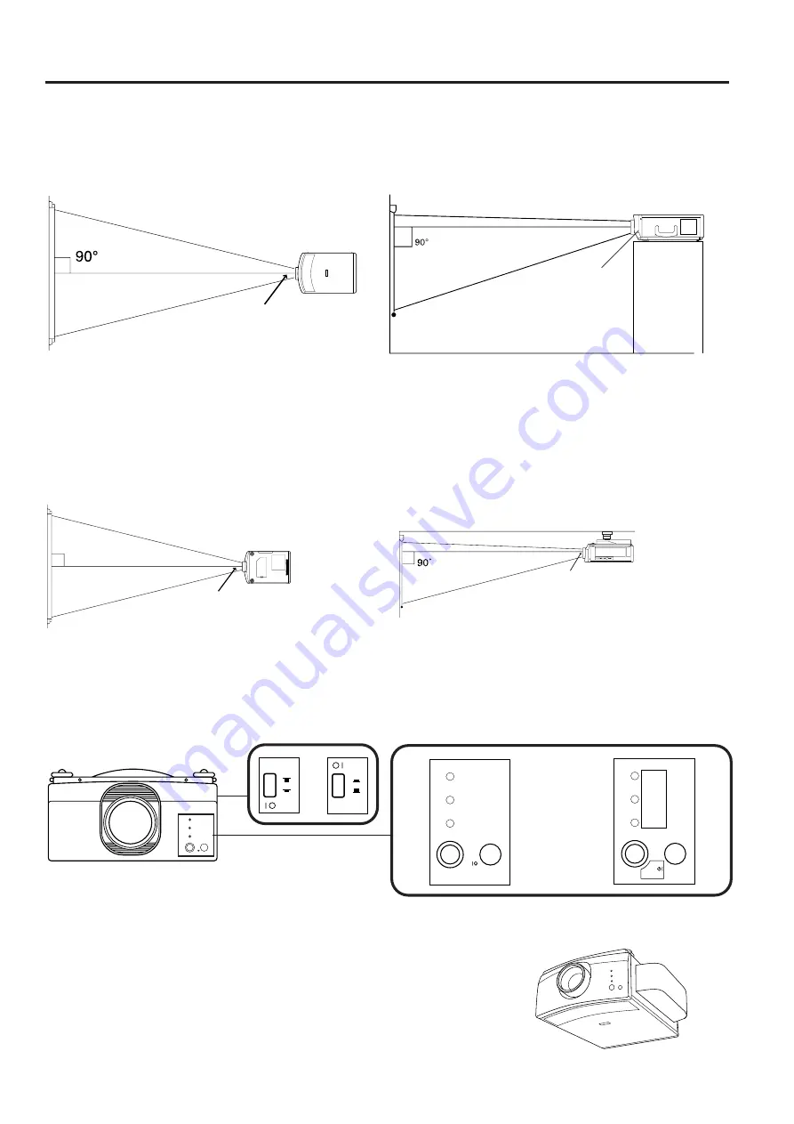
Inverted Labeling for Ceiling Mount

• When ceiling mounting the projector, attach the supplied inverted label as shown.

ON/OFF

POWER

LAMP

TEMP.

ON/OFF

POWER

LAMP

TEMP.

ON/OFF

POWER

LAMP

TEMP.

Front

Example of a ceiling-mount setup

Before mounting the projector, be sure to contact your nearest Authorized Sharp Industrial LCD Products Dealer to
obtain the manufacturer recommended ceiling mount bracket (sold separately). (AN-XGCM20 Ceiling Mount
Bracket, AN-EP101AP Extension Tube).

If the relative positions of the projector and the screen are not properly adjusted, the picture will be distorted.

MENU

ENTER

LENS

E-ZOOM

MUTE

VOLUME

INPUT

SELECT

MN

LN

E-Z

IN

ADJ.

EN

90˚

SIDE VIEW

TOP VIEW

Lens center

Lens center

Example of a high-mount setup

• A high-mount setup makes projection from an elevated location possible, without ceiling modifications.

Lens center

©

Lens center

SIDE VIEW

TOP VIEW

Terminal Cover

• When the projector is ceiling mounted, attach the terminal cover

(supplied) to hide the connecting cables.

• Use the terminal cover to hide the connecting cables when the

projector is used on a desktop or high mounted.

ON

OFF

ON

OFF

Содержание XG-E1200U

Страница 1: ...nefit of the parts service and labor warranty applicable to your purchase 2 CONSUMER PRODUCT SAFETY ACT To ensure that you will promptly receive any safety notification of inspection modification or recall that SHARP may be required to give under the 1972 Consumer Product Safety Act PLEASE READ CAREFULLY THE IMPORTANT LIMITED WARRANTY CLAUSE U S A ONLY WARNING High brightness light source do not s...

Страница 2: ...y the product manufacturer as they may cause hazards 7 Water and Moisture Do not use this product near water for example near a bathtub wash bowl kitchen sink or laundry tub in a wet basement or near a swimming pool and the like 8 Accessories Do not place this product on an unstable cart stand tripod bracket or table The product may fall causing serious injury to a child or adult and serious damag...

Страница 3: ... be sure the service technician has used replace ment parts specified by the manufacturer or with the same characteristics as the original part Unauthorized substitutions may result in fire electric shock or other hazards 20 Safety Check Upon completion of any service or repairs to this product ask the service technician to perform safety checks to determine that the product is in proper operating...

Страница 4: ...deo images Can be projected directly onto a video screen or white wall Lightweight convergence free system for easy installation DIRECT COMPUTER COMPATIBILITY A multi scan RGB Input accepts signals from XGA 1 024 dots 768 lines compressed SVGA 800 dots 600 lines VGA and Mac 832 dots 624 lines maximum compatible computers without the need for any additional hardware FLEXIBLE USE In addition to the ...

Страница 5: ...s The exhaust vent the lamp cage cover and adjacent areas may be extremely hot during projector operation To prevent injury do not touch these areas until they have sufficiently cooled Allow at least 4 10 cm of space between the cooling fan exhaust vent and the other nearest wall or obstruction If the cooling fan becomes obstructed a protection device will automatically turn off the projector lamp...

Страница 6: ...K ENTER button SIDE VIEW Wireless Mouse Remote Control FRONT VIEW INPUT SELECT buttons INPUT CHECK button Note If the MAIN POWER switch on the remote control is left on for more than 10 minutes without operation the power will automatically turn off To turn the power back on press any button on the remote control for at least one second ADJ label Remote control handling precautions The laser beam ...

Страница 7: ...hey may run out after a short time If so replace them with new batteries as soon as possible Remote control positioning Use the remote control as shown in the figures on the left Note The signal from the remote control can be reflected off the screen for easy operation However the effective distance of the signal may differ due to the screen material REAR VIEW Insert the side tabs into their slots...

Страница 8: ...B COMPUTER WIRED REMOTE FOR PC98 MOUSE PC CONTROL AUDIO INPUT VIDEO INPUT VIDEO OUTPUT MENU ENTER LENS E ZOOM MUTE VOLUME INPUT SELECT MN LN E Z IN ADJ EN Projector Functions and Operations LEFT CLICK button The LEFT CLICK button on the back of the remote control corresponds to the left button of the mouse on two button mouse systems RIGHT CLICK button The RIGHT CLICK button on the front of the re...

Страница 9: ...eft You can adjust the picture as shown on the left by pressing the ADJUSTMENT or buttons while in ADJUST mode Note Do not attempt to adjust the lens by hand as it may damage the lens mechanism Adjust the focus until the picture on the screen is sharp The focus pattern appears on the screen The picture can be adjusted to the desired size within the zoom lens range The picture can be adjusted withi...

Страница 10: ...7 9 in 120 cm 15 1 in 113 cm 14 3 in 111 cm 13 1 in 18 cm 12 0 in 15 cm Upper lens shift position 326 4 in 829 cm 261 3 in 664 cm 195 7 in 497 cm 130 6 in 332 cm 97 9 in 249 cm 65 1 in 165 cm 52 3 in 133 cm 39 1 in 99 cm 26 0 in 66 cm Distance from lens center to lower edge of screen H Picture size diag 500 inches 400 inches 300 inches 200 inches 150 inches 100 inches 80 inches 60 inches 40 inches...

Страница 11: ...F F O F F O N E Z O O M O F F O F F S E L A D J E N D M E N U B L A C K S C R E E N I M A G E A D J R E V E R S E I N P U T D I S P L A Y O F F O F F O F F E Z O O M O N O F F S E L A D J E N D MENU I N V E R T B L A C K S C R E E N I M A G E A D J R E V E R S E I N V E R T I N P U T D I S P L A Y O F F O F F O N E Z O O M O N O F F S E L A D J E N D MENU 4 4 Reversed Inverted Image Mode In the IM...

Страница 12: ...ned when the projector is at a 90 degree angle to the screen Position the projector and screen as shown SIDE VIEW TOP VIEW The projector lens should be centered in the middle of the screen If the projector and screen are not centered properly the picture will be distorted making viewing difficult Lens center Using the horizontal reverse function makes the following setups possible Example of a rev...

Страница 13: ...P Extension Tube If the relative positions of the projector and the screen are not properly adjusted the picture will be distorted MENU ENTER LENS E ZOOM MUTE VOLUME INPUT SELECT MN LN E Z IN ADJ EN 90 SIDE VIEW TOP VIEW Lens center Lens center Example of a high mount setup A high mount setup makes projection from an elevated location possible without ceiling modifications Lens center Lens center ...

Страница 14: ...e the projector once you are sure the adjuster legs have locked in position 3 Make any minor adjustments necessary Turn the adjusters to further adjust the angle of the projector Returning the projector to its original position While holding the projector with both hands press the adjuster release and slowly lower the projector to its original position Notes Adjustable up to approximately 5 from t...

Страница 15: ...ecting to video equipment in order to protect both the projector and the equipment being connected Used when the AV equipment to be connected has an S VIDEO output terminal To audio output terminals To audio input terminals To video input terminal Notes Note the following when using the S VIDEO INPUT terminal The S VIDEO INPUT terminal uses a video signal system in which the picture is separated i...

Страница 16: ... pages 35 and 36 for details By connecting the projector mouse terminal to your personal computer s mouse terminal using the supplied mouse control cables you can use the remote control in place of the computer s mouse Refer to page 8 for details Notes The wireless mouse or RS 232C function may not operate if your computer port is not correctly set up Please refer to your computer owners manual fo...

Страница 17: ... and 2 to ON and 3 4 5 and 6 to OFF For 832 624 resolution set switches 2 and 4 to ON and 1 3 5 and 6 to OFF 2 Connect the supplied Macintosh adaptor to the RGB signal output terminal on your Macintosh Series computer as shown on the left and secure the plugs by tightening the thumb screws 3 Firmly plug the supplied RGB signal cable into both the RGB input terminal on the projector and the Macinto...

Страница 18: ...projector to the monitor should be the same as the input signal from the computer to the projector Example Input 13 14 640 480 Output 640 480 Input 16 17 832 624 Output 832 624 Note The supplied adaptor is only for use with H SYNC and V SYNC output No picture will appear when connected to monitors that only use C SYNC Notes When using the projector with an external IBM PC monitor connect the monit...

Страница 19: ...NC VGA cable sold separately directly from the input terminals on the projector to the computer S VIDEO VIDEO L R FILTER R G B H L R V ON OFF DC5V OUTPUT MAX CURRENT 1A COMPUTER AUDIO IN AUDIO OUTPUT OUTPUT INPUT2 INPUT1 RGB COMPUTER WIRED REMOTE FOR PC98 MOUSE PC CONTROL AUDIO INPUT VIDEO INPUT VIDEO OUTPUT Playback To RGB Switcher Sold separately To R G B H SYNC and V SYNC output terminals To au...

Страница 20: ...1 0 4 0 1 6 5 0 1 4 4 3 1 8 2 3 1 2 1 3 1 4 6 8 6 9 8 2 5 1 1 µs 4 7 7 7 1 3 6 7 7 7 1 3 3 1 4 6 2 4 4 4 8 2 0 0 4 6 2 0 0 8 0 2 3 3 3 1 2 7 7 6 0 2 7 0 7 7 1 0 6 6 6 1 4 1 7 5 8 2 5 9 5 8 2 4 2 1 0 2 t o d 1 s n 2 8 0 3 5 3 9 1 2 7 9 3 6 4 7 1 3 7 7 7 7 2 0 0 0 5 2 0 0 0 0 2 2 0 2 0 2 5 8 3 5 1 3 3 1 7 2 1 8 8 6 0 3 3 3 6 0 4 1 9 1 3 8 6 4 7 1 1 H z H k 9 8 6 4 1 3 8 8 6 4 1 3 0 6 8 7 3 6 5 1 5 3...

Страница 21: ... left or right VERTICAL POSITION ADJUSTMENT UP DOWN Used to center the on screen image by moving it up or down MODE ADJUSTMENT Connecting to IBM PC Computers Ordinarily the type of input signal is detected and the correct resolution mode Text or Graphics is automatically selected However for the following signals set MODE to ON or OFF to select the projector s resolution mode to match the computer...

Страница 22: ...ER indicator is not lit the remote control cannot be used to operate the projector If the power is turned on immediately after it has been turned off it may take a short while before the lamp turns on During this period the LAMP REPLACEMENT indicator flashes After the projector is unpacked and turned on for the first time a slight odor may be emitted from the exhaust fan This odor will soon disapp...

Страница 23: ...e SYSTEM 4 Press the ADJUSTMENT buttons to highlight yellow the video system desired yellow Then press the ENTER button to set the system Notes In AUTO mode PAL SECAM or NTSC is displayed on the screen for a few seconds when the mode is changed with the INPUT SELECT button When the system mode is set to AUTO you may not receive a clear picture due to signal differences If this happens switch to th...

Страница 24: ...he projector or remote control The power can be temporarily turned off by pressing the POWER ON OFF button on either the projector or remote control The POWER indicator will turn red and the cooling fan will run for 90 seconds then the power will turn off and the projector will return to STANDBY mode The power can be turned on again either from the projector or remote control When the power is tur...

Страница 25: ... the selected item will be displayed Press the ADJUSTMENT buttons to move the mark of the selected adjustment item to the desired setting The adjustment mode is displayed for about 30 seconds Notes When a VIDEO signal input has been selected only PIC TURE BRIGHT COLOR TINT and SHARPNESS can be adjusted TINT only appears in NTSC mode 4 Press the MENU button anytime to exit RGB ADJ ADJUSTMENT button...

Страница 26: ...utton While the MENU screen is displayed press the ADJUSTMENT buttons to select RGB1 ADJ Press the ENTER button The MENU mode changes as shown While the RGB adjustment menu is displayed press the ADJUSTMENT buttons to select MEMORY SELECT Then press the ENTER button to change the image 2 Press the ADJUSTMENT buttons The screen shown on the left will appear There are 7 memory positions Press the AD...

Страница 27: ...UDIO with the ADJUSTMENT buttons Then press the ENTER button to change to the picture indicated on the left Select BALANCE TREBLE or BASS with the ADJUSTMENT buttons Adjust the mode you want with the ADJUSTMENT buttons To return to the factory preset mode press the AD JUSTMENT buttons to select RESET then press the ENTER button Description of Adjustment Items On Screen Display A U D I O T R E B L ...

Страница 28: ...ode an enlarged display increases the amount of data processed on the screen and a compressed image decreases the number of lines displayed which may make characters difficult to read 2 Press the E ZOOM button on the remote control The E ZOOM button on the remote control can be used to select E ZOOM and NO E ZOOM modes Note In SVGA 800 600 dots or Mac 16 832 624 dots mode appears indicating the E ...

Страница 29: ...MENU screen is displayed press the ADJUSTMENT buttons to select RGB1 ADJ Press the ENTER button The MENU mode changes as shown 3 While the RGB adjustment menu is displayed press the ADJUSTMENT buttons to select MEMORY SELECT Then press the ENTER button to change the image 4 The screen shown on the left will appear 5 Press the ADJUSTMENT button once to move to the following screen 6 Using the ADJUS...

Страница 30: ...isplay the IMAGE ADJ screen shown Press the ADJUSTMENT buttons to select BLACK SCREEN and press the ADJUSTMENT buttons to select ON Then press the MENU button to display the black screen Note When BLACK SCREEN is set to OFF the screen will change to the presentation image when you press the MENU button On Screen Display B L A C K S C R E E N I M A G E A D J R E V E R S E I N V E R T I N P U T D I ...

Страница 31: ...RGB mode When the power is turned off the POWER indicator will light red To turn the power on again press the POWER button to set it to OFF then press it again to set it to ON On Screen Display Using the On Screen Display Override Function The On Screen Displays RGB 1 024 768 60Hz etc that appear during input select can be turned off Once INPUT DISPLAY is turned off the On Screen Displays will not...

Страница 32: ...lean the dust off the air filter and cover with a vacuum cleaner extension hose Clean the AIR FILTER 5 Replace the AIR FILTER Replace the FILTER COVER 1 3 Turn OFF the MAIN POWER 2 Remove the FILTER COVER Remove the AIR FILTER Grasp the air filter between your fingers and lift it out of the filter cover Press the tab in the direction of the arrow and lift open the filter cover Press Tab Open ON OF...

Страница 33: ...roperly inserted The main power of the remote control is not turned on The remote control s MOUSE ADJUSTMENT switch is set to MOUSE The lamp has reached the end of its operating life See page 33 Cables improperly connected to side panel of the projector See pages 15 16 17 18 and 19 The BRIGHTNESS and PICTURE adjustments are set to minimum position See page 25 The COLOR and TINT adjustments are not...

Страница 34: ...ted to internal circuit 6 DR Data Set Ready Output Not connected 7 RS Request to Send Output Connected to internal circuit 8 CS Clear to Send Input Connected to internal circuit 9 CI Ring Indicator Input Connected to internal circuit Mouse Input Terminal for IBM Mac 9 pin D sub female connector Pin No Signal I O Reference 1 5V Input Computer output 2 XA Input Computer output 3 XB Input Computer ou...

Страница 35: ... to the computer Therefore confirm the conditions by transmitting the display commands for each adjustment menu and checking the conditions with the On Screen Display If the unit receives a command other than a menu display command it will execute the command without displaying the On Screen Display 4 Commands Note If a dash appears in the parameter column enter a space If an asterisk appears ente...

Страница 36: ...SE OFF _ _ _ 1 REVERSE ON I M I N _ _ _ 0 INVERT OFF _ _ _ 1 INVERT ON VIDEO CONFIRMATION S Y S E _ _ _ 0 DISPLAY MOUSE ADJUSTMENT R E M O I A R E I M E Z I M B E I M B K I M D I I M R E I M I N R E M O _ _ _ 1 1 REMOTE MOUSE AT _ _ _ 2 REMOTE MOUSE 98 DC 5V OUTPUT D C 5 V D C 5 V _ _ _ 0 WHEN LAMP IS ON _ _ _ WHEN MAIN POWER IS ON RGB 1 ADJUSTMENT R A P I _ PICTURE 30 30 R A B R _ BRIGHT 30 30 R ...

Страница 37: ...mote control signal format 1 Transmission format a 15 bit format 2 Wave form of output signal Output using Pulse Position Modulation 0 1 0 D 0 0 0 1 T0 T1 t t 264 µs To 1 05 ms T1 2 10 ms Pulse carrier frequency 455 12 kHz Duty ratio 1 1 3 Transmission control code a 15 bit Note To operate the MOUSE L CLICK and R CLICK functions through the wired remote control input connect the cable from the wir...

Страница 38: ...ntal sync signal TTL level positive negative or composite sync Apple only Vertical sync signal Same as above 9 pin D sub male connector for controlling personal computer 9 pin D sub female connector for wireless mouse 9 pin mini DIN connector for wireless mouse 3 8 cm round 2 AC 120 V 50 60 Hz 520 W 41 F to 104 F 5 C to 40 C 4 F to 140 F 20 C to 60 C Plastic 40 kHz Wave length 670 nm Max output 1 ...

Страница 39: ...8 528 7 7 195 11 7 296 0 2 6 0 2 4 ø4 4 ø111 ø1 8 ø45 3 5 89 4 5 116 7 13 2 335 1 8 46 3 7 93 4 4 6 118 4 2 107 5 Rear View Dimensions Lens at upper shift Lens at lower shift Lens extended Lens housed Front View Side View Bottom View Units inches mm Top View ...

Отзывы: