


UX- A1000U
7 – 1
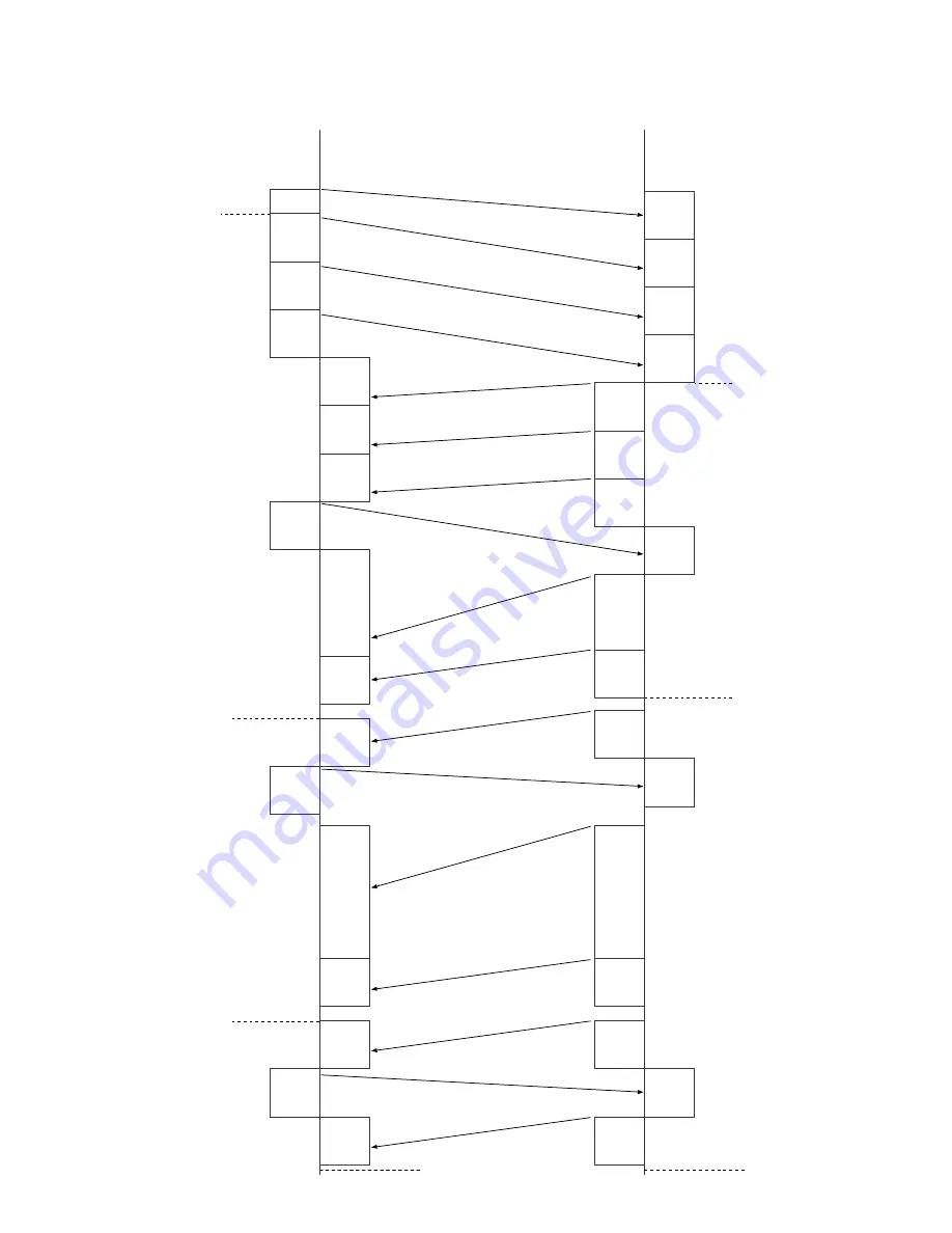
CHAPTER 7. OPERATION FLOWCHART
[1] Protocol
NSF
DIS
NSS
TCF
CED
NSF
DIS
NSS
TCF
RTC
MPS
CFR
RTC
MPS
MCF
RTC
EOP
MCF
MCF
DCN
CFR
TSI
CSI
CSI
TSI
RTC
EOP
MCF
DCN
IMAGE
SIGNAL
Document ejected
Recording paper ejected
Receive side
G3 communication
CED
Transmitter side
(Document inserted into
document sensor during
standby)
To recording
position
(DCS)
Cut line printed
IMAGE
SIGNAL
Cut line printed
IMAGE
SIGNAL
IMAGE
SIGNAL
Next page insert
command
1st page
Document inserted to
the reading position
(DCS)
Содержание UX-A1000
Страница 51: ...UX A1000U 3 13 M E M O ...
Страница 81: ...UX A1000U Control PWB parts layout Top side 6 8 DRSNS BROWN ORGSNS ORANGE FRSNS RED ...
Страница 82: ...UX A1000U Control PWB parts layout Bottom side 6 9 FU101 FU100 ...
Страница 86: ...UX A1000U TEL LIU PWB parts layout Top side 6 13 TEL LIU PWB parts layout Bottom side ...
Страница 91: ...UX A1000U P IN YELLOW FU1 GREEN 3 3V Printer PWB parts layout Top side 6 18 ...
Страница 92: ...UX A1000U Printer PWB parts layout Bottom side 6 19 ...
Страница 94: ...UX A1000U Power supply PWB parts layout Top side 6 21 Power supply PWB parts layout Bottom side ...
Страница 98: ...UX A1000U FPC FPC Ink PWB parts layout Top side Ink PWB parts layout Bottom side 6 25 ...


