background image

21

R-1610
R-1611
R-1612

REF. NO.

PART NO.

§

DESCRIPTION

Q'TY CODE

RY1-2

RRLY-A113DRE0

M

Relay (DU24D1-1PR(M))

2

AG

RY3-4

RRLY-B004MRE0

M

Relay (FTR-F3AA024E)

2

AG

RY5

RRLY-A112DRE0

M

Relay (VE24HSE-K)

1

AH

SSR1

RTR--A001DRE0

M

Solid state relay

1

AG

SP1

RALM-A014DRE0

J

Buzzer (PKM22EPT)

1

AG

T1

RTRNPB017MRE0

M

Transformer

1

BE

VRS1

RH-VZA032DRE0

J

Varistor (10G471K)

1

AE

ZD1

VHEHZ161///-1

J

Zener diode (HZ-161)

1

AA

3- 2

FPNLCB263MRK0

M

Control panel sub. assembly [R-1610]

1

3- 2

FPNLCB264MRK0

M

Control panel sub, assembly [R-1611]

1

3- 2

FPNLCB265MRK0

M

Control panel sub, assembly [R-1612]

1

3- 2-1

FUNTKB213MRE0

M

Key unit [R-1610]

1

3- 2-1

FUNTKB214MRE0

M

Key unit [R-1611]

1

3- 2-1

FUNTKB215MRE0

M

Key unit [R-1612]

1

3- 2-2

GMADIB033MRF0

M

Display window [R-1611]

1

AK

3- 2-2

GMADIB033MRF0

M

Display window [R-1612]

1

AK

3- 2-2

GMADIB034MRR0

M

Display window [R-1610]

1

AK

3- 2-3

XEPSD30P10XS0

M

Screw; 3mm x 10mm

1

AB

3- 3

LHLD-B011MRF0

M

LCD holder

1

AD

3- 4

PSHEPB027MRE0

M

LED sheet

1

AF

3- 5

XEPSD30P10XS0

M

Screw; 3mm x 10mm

2

AB

OVEN PARTS

4- 1

FFTA-B003MRK0

M

Exhaust damper assembly

 1

AH

4- 2

FROLPB025MRK0

M

Turntable support  assembly

 1

AN

4- 3

NTNT-A090WRE0

M

Turntable tray

 1

AN

4- 4

LANGKB010MRP0

M

Capacitor holder

 1

BB

4- 5

FCOVPB016MRK0

M

Stirrer cover assembly

 1

AN

4- 6

FFAN-B010MRK0

M

Stirrer fan assembly

 1

AH

4- 7

*************

M

Oven cavity (Not replaceable part)

 1

--

4- 8

PPACGB014MRF0

M

Turntable motor packing

 1

AA

4- 9

PHOK-B017MRF0

M

Latch hook

 1

AG

4-10

LANGTB036MRP0

M

Unit mounting plate

 1

AP

4-11

NFANPB001MRE0

M

Fan blade

 1

AC

4-12

LBSHC0037WRE0

M

Cord bushing

 1

AB

4-13

PCOVPB065MRP0

M

Oven lamp cover

 1

AD

4-14

PDUC-B095MRP0

M

Hood intake duct R

 1

AM

4-15

PCUSUB039MRP0

M

Hood intake duct cushion

 1

AA

4-16

PFILWB005MRP0

M

Lamp filter

 1

AB

4-17

LANGTB046MRP0

M

Chassis support left

1

AD

4-18

LANGTB040MRP0

M

Chassis support right

 1

AE

4-19

PDUC-B094MRF0

M

Hood duct

 1

AL

4-20

LHLD-B012MRF0

M

Rack holder

 4

AF

4-21

LSTPPB031MRF0

M

Door stopper

 1

AC

4-22

PCOVPB076MRF0

M

Louver cover A [R-1610]

 1

AG

4-23

PCOVPB077MRF0

M

Louver cover B [R-1610]

 1

AG

4-24

PCOVPB078MRF0

M

Louver cover C [R-1610]

 1

AG

4-25

PDUC-B098MRP0

M

Magnetron air guide

 1

AC

DOOR PARTS

5- 1

FDORFB060MRT0

M

Door panel assembly

 1

AX

5- 2

FCOV-B146MRK0

M

Door frame assembly [R-1610]

1

BD

5- 2

FCOV-B145MRK0

M

Door frame assembly [R-1611]

1

BD

5- 2

FCOV-B147MRK0

M

Door frame assembly [R-1612]

1

BC

5-2-1

PGLSPB012MRE0

M

Front door glass [R-1610]

1

AQ

5-2-1

PGLSPB014MRR0

M

Front door glass [R-1611]

1

AQ

5-2-1

PGLSPB013MRR0

M

Front door glass [R-1612]

1

AQ

5-2-2

LSTPPB030MRF0

M

Latch head

1

AC

5-2-3

LSTPPB032MRF0

M

Glass stopper

1

AC

5-2-4

MSPRTA046WRE0

M

Latch spring

1

AB

5-2-5

GWAKPB105MRR0

M

Door frame [R-1610]

 1

AZ

5-2-5

GWAKPB104MRR0

M

Door frame [R-1611]

 1

AZ

5-2-5

GWAKPB106MRR0

M

Door frame [R-1612]

 1

AV

5- 3

FCOVHB005MRK0

M

Choke cover assembly

1

AH

5- 4

PSHEPB024MRE0

M

Sealer film

 1

AF

5- 5

FHNDPB002MRK0

M

Door handle assembly [R-1610]

 1

AL

5- 5

FHNDPB001MRK0

M

Door handle assembly [R-1611]

 1

AL

5- 5

FHNDPB003MRK0

M

Door handle assembly [R-1612]

 1

AL

5- 6

XCPSD40P08000

M

Screw : 4mm x 8mm

 4

AA

5- 7

XCPSD40P12000

M

Screw : 4mm x 12mm

 2

AA

Содержание R-1610

Страница 1: ...DURE 14 PICTORIAL DIAGRAM 16 POWER UNIT CIRCUIT 17 LSI UNIT CIRCUIT 18 INDICATOR CIRCUIT 19 PARTS LIST 20 PACKING AND ACCESSORIES 25 S5911R1610X R 1610 R 1611 R 1612 MODELS SUPPLEMENTAL SERVICE MANUAL SHARP CORPORATION This document has been published to be used for after sales service only The contents are subject to change without notice This is a supplemental Service Manual for Models R 1610 R ...

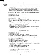
Страница 2: ...eration and transmission systems shall be repaired replaced or adjusted by procedures described in this manual before the oven is released to the owner e A microwave leakage check to verify compliance with the Federal Performance Standard should be performed on each oven prior to release to the owner BEFORE SERVICING Before servicing an operative unit perform a microwave emission check as per the ...

Страница 3: ...ge capacitor 4 Disconnect the leads to the primary of the power transformer 5 Ensure that these leads remain isolated from other components and oven chassis by using insulation tape 6 After that procedure reconnect the power supply cord When the testing is completed 1 Disconnect the power supply cord and then remove outer case 2 Open the door and block it open 3 Discharge high voltage capacitor 4 ...

Страница 4: ... of the oven cavity The water container shall be a low form of 600 ml 20 oz beaker with an inside diameter of approx 8 5 cm 3 1 2 in and made of an electrically nonconductive material such as glass or plastic The placing of this standard load in the oven is important not only to protect the oven but also to insure that any leakage is measured accurately 4 Set the cooking control on Full Power Cook...

Страница 5: ... radiation hazard WARNING Never operate the oven until the following points are ensured A The door is tightly closed B The door brackets and hinges are not defective C The door packing is not damaged D The door is not deformed or warped E There is not any other visible damage with the oven Servicing and repair work must be carried out only by trained service personnel DANGER Certain initial parts ...

Страница 6: ...90 approx 90 of Full Power P 80 approx 80 of Full Power P 70 approx 70 of Full Power P 60 approx 60 of Full Power P 50 approx 50 of Full Power P 40 approx 40 of Full Power P 30 approx 30 of Full Power P 20 approx 20 of Full Power P 10 approx 10 of Full Power P 0 No power throughout the cooking time Sensor Cooking pads Breakfast Bar pad Lunch on the Run pad One Dish Dinners pad Super Defrost pad Co...

Страница 7: ...PIN FROM THE PLUG The power supply cord and plug must be connected to a separate 120 Volt AC 60 Hz 15 Amp or more dedicated line using a grounded receptacle The receptacle should be located inside the cabinet directly above the Microwave Oven Hood system mounting location 3 Pronged Plug Grounded Receptacle Box Grounding Pin 3 Pronged Receptacle CONTROL PANEL SENSOR DEFROST TURNTABLE COOK OFF HELP ...

Страница 8: ...e 1 Touch one of the Sensor Cooking pads And then touch START TOUCH ON pad NOTE TheovenshouldnotbeoperatedonSensorCooking immediately after plugging in the unit Wait two minutes before cooking on Sensor Cooking 2 The coil of shut off relays RY1 and RY3 are energized the oven lamp turntable motor and cooling fan motor are turned on but the power transformer is not turned on 3 Afterabout32seconds th...

Страница 9: ...GRN HOOD MOTOR B7 B5 B3 B1 A1 A3 B9 A7 A5 N O F1 F2 F3 E1 E2 DOOR SENSING SWITCH SECONDARY INTERLOCK SWITCH 120 V AC 60 Hz HOOD LAMP HL HL RY3 RY1 RY2 PRIMARY INTERLOCK RELAY SSR FM STM OL TTM HOOD FAN THERMAL CUT OUT HOOD CAPACITOR RY4 RY5 N C Low High MAGNETRON TEMPERATURE FUSE FUSE 20A TURNTABLE MOTOR FAN MOTOR STIRRER MOTOR MAGNETRON OVEN LAMP MONITOR SWITCH BLK WHT AH SENSOR POWER TRANSFORMER...

Страница 10: ...nt 1 Disconnect the power supply cord and then remove outer case 2 Open the door and block it open 3 Discharge high voltage capacitor 4 Disconnect the leads to the primary of the power transformer 5 Ensure that the leads remain isolated from other components and oven chassis by using insulation tape 6 After that procedure reconnect the power supply cord When the testing is completed 1 Disconnect t...

Страница 11: ...nventional surface unit Refer to the INSTALLATION INSTRUCTIONS of the operation manual 4 Exhaust vents are provided on the back of the unit for proper cooling and air flow in the cavity To permit adequate ventilation be sure to install so as not to block these vents There should be some space for air circulation 5 Be sure the exterior of the cooking container and the interior of the oven are dry W...

Страница 12: ...fter the water is boiling bubbling If new sensor dose not operate properly the problem is with the control unit and refer to explanation below CHECKING CONTROL UNIT 1 Disconnect the power supply cord and then remove outer case 2 Open the door and block it open 3 Discharge high voltage capacitor 4 Disconnect the sensor connector that is mounted to control panel 5 Then connect the dummy resistor cir...

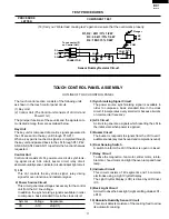
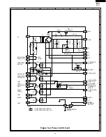
Страница 13: ...Display LCD is drived by LCD driver IC3 9 Back Light Circuit A circuit to drive the back light Light emitting diodes LD1 LD10 10 Absolute Humidity Sensor Circuit This circuit detects moisture of the cooking food to allow its automatic cooking The touch control section consists of the following units as shown in the touch control panel circuit 1 Key Unit 2 Control Unit The Control unit consists of ...

Страница 14: ...gnal is input to AN8 AN9 AN10 AN11 P41 and P42 terminal while one of G2 line keys on key matrix is touched 11 P17 OUT Key strobe signal Signal applied to touch key section A pulse signal is input to AN9 AN10 AN11 P41 and P42 terminal while one of G1 line keys on key matrix is touched 29 P32 OUT Terminal not used 30 34 P33 P37 OUT Used for initial balancing of the bridge circuit absokute humidity s...

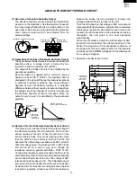
Страница 15: ...s as shown in the illustration One thermistor is housed in the closed vessel filled with dry air while another in the open vessel Each sensor is provided with the protective cover made of metal mesh to be protected from the external airflow 2 Operational Principle of Absolute Humidity Sensor Thefigurebelowshowsthebasicstructureofanabsolute humidity sensor A bridge circuit is formed by two thermist...

Страница 16: ... from the hood duct by lifting it up 6 Now the hood fan motor is free 7 Disconnect the connector CN F from the control unit 8 Remove one 1 screw holding the hood duct to the oven cavity front plate 9 Release the 6 pin connector and the 3 pin connector of the main harness A from the hood duct 10 Disconnectthewireleadsfromthefanmotorandchassis support and release the wire leads from holes of the hoo...

Страница 17: ...gle 17 Pull the wire leads from the oven lamp socket by pushing the terminal hole of the oven lamp socket with a small flat type screw driver 18 Now the oven lamp socket is free 19 Release the harness of the AH sensor assembly from three 3 wire holders of the hood duct 20 Remove two 2 screws holding the AH sensor assembly to the hood duct 21 Now the AH sensor assembly is free ...

Страница 18: ...is Support CN E GRY WHT WHT WHT BLU WHT WHT WHT BLK SECONDARY INTERLOCK SWITCH N O N C COM COM MONITOR SWITCH FUSE HOLDER N O N O GRN RED N O COM DOOR SENSING SWITCH CN B CN E CN F CN C CN G CN C CN A 1 9 1 1 1 14 1 3 2 7 PRIMARY INTERLOCK RELAY RY1 RY3 RY2 RY4 RY1 N O RY1 COM RY2 N O RY2 COM GRY C100 T1 HOOD FAN MOTOR STIRRER MOTOR 1 2 3 4 5 6 WHT RED YLW BLU BLK WHT RED YLW BLU BLK 1 2 RED GRN 1...

Страница 19: ...0v C4 10µ 35v C2 1000µ 35v R5 4 7k R1 2 4k C100 7µ 230v AC MOTOR RUN CAPACITOR TURNTABLE MOTOR TURNTABLE MOTOR LED GND VC VA VR INT BUZZER HOOD LAMP HOOD MOTOR HIGH LOW HOOD MOTOR COM MICRO DOOR SENSING SWITCH N C OVEN LAMP FAN MOTOR TURNTABLE MOTOR HOOD LAMP OVEN LAMP FAN MOTOR COM COM COM NOTE IF NOT SPECIFIED 1SS270A IF NOT SPECIFIED 1 4W 5 MICRO LOW HOOD MOTOR HOOD THEMO HIGH C110 0 033µ 250v ...

Страница 20: ... R74 270k R80 1M C110 4 7k ZD10 UDZ4 3B R11 15k J10 J11 4 7K J13 4 7K J15 4 7K J17 4 7K J12 J14 J16 R66 15k R65 15k R64 15k R63 15k R62 15k R61 15k R60 15k R67 15k C13 0 01µ 25v C14 0 01µ 25v C40 0 01µ 25v C93 0 01µ 25v C92 0 01µ 25v C64 330p 50v C65 330p 50v C63 330p 50v C62 330p 50v C61 330p 50v C60 330p 50v Q11 DTA143EKA D90 MA152WA Q25 DTA143EKA Q24 DTA143EKA Q23 DTA143EKA CF1 CST4 00MGW Q30 D...

Страница 21: ...16 COM15 COM14 COM13 COM12 COM11 COM10 COM9 SEG40 SEG39 SEG38 SEG37 SEG36 SEG35 SEG34 SEG33 SEG32 SEG31 SEG30 SEG29 SEG28 SEG27 SEG26 SEG25 SEG24 SEG23 SEG22 SEG21 SEG20 SEG19 SEG18 SEG17 SEG16 SEG15 SEG14 SEG13 SEG12 SEG11 SEG10 SEG9 SEG8 SEG7 SEG6 SEG5 SEG4 SEG3 SEG2 SEG1 COM1 COM2 COM3 COM4 COM5 COM6 COM7 COM8 VDD N C N C RESET TEST VREF R03 R02 R01 R00 P13 P12 P11 P10 P03 P02 P01 P00 K03 K02 K...

Страница 22: ...PCB052MRR0 M Schematic diagram 1 AB 2 7 FANGKB009MRY0 M Hood lamp glass assembly R 1610 1 AN 2 7 FANGKB010MRY0 M Hood lamp glass assembly R 1611 1 AM 2 7 FANGKB011MRY0 M Hood lamp glass assembly R 1612 1 AM 2 7 1 LANGQB016MRP0 M Hood lamp glass angle R 1610 1 AG 2 7 1 LANGQB020MRP0 M Hood lamp glass angle R 1611 1 AG 2 7 1 LANGQB027MRP0 M Hood lamp glass angle R 1612 1 AG 2 7 2 PGLSPB004MRE0 M Hoo...

Страница 23: ...P0 M Unit mounting plate 1 AP 4 11 NFANPB001MRE0 M Fan blade 1 AC 4 12 LBSHC0037WRE0 M Cord bushing 1 AB 4 13 PCOVPB065MRP0 M Oven lamp cover 1 AD 4 14 PDUC B095MRP0 M Hood intake duct R 1 AM 4 15 PCUSUB039MRP0 M Hood intake duct cushion 1 AA 4 16 PFILWB005MRP0 M Lamp filter 1 AB 4 17 LANGTB046MRP0 M Chassis support left 1 AD 4 18 LANGTB040MRP0 M Chassis support right 1 AE 4 19 PDUC B094MRF0 M Hoo...

Страница 24: ... PFIL B002MRE0 M Grease filter 2 AF 6 14 PCLICB003MRE0 M Canoe clip 1 AA 6 15 UAMI B009MRM0 M Rack 1 AR 6 16 TLAB B039MRR0 M Menu label 1 6 17 QW VZB009MRE0 M Sensor ground wire 1 SCREWS NUTS AND WASHERS 7 1 XCPSD40P08000 M Screw 4mm x 8mm 2 AA 7 2 XOTSF40P12000 M Screw 4mm x 12mm R 1610 4 AB 7 2 XOTSE40P12000 M Screw 4mm x 12mm R 1611 4 AA 7 2 XOTSD40P12000 M Screw 4mm x 12mm R 1612 4 AA 7 3 XOTS...

Страница 25: ... 7 8 1 17 4 17 7 3 7 9 7 9 4 15 1 10 7 11 4 9 1 10 1 9 7 6 7 7 7 7 1 8 7 10 2 3 2 2 4 6 4 5 4 3 6 13 2 8 1 2 4 14 4 18 6 13 4 2 1 16 1 13 6 14 4 10 7 5 4 11 1 15 4 12 7 3 4 7 4 23 4 24 4 20 4 8 1 4 1 6 1 7 7 8 4 4 1 5 1 3 6 8 4 25 7 3 1 11 7 3 7 3 1 1 7 2 2 4 2 7 1 2 7 2 7 2 2 7 6 9 6 8 4 16 6 12 4 22 1 14 1 18 6 17 x2 4 20 6 16 x2 OVEN AND CABINET PARTS ...

Страница 26: ...A B C D E F G H A B C D E F G H 5 6 5 4 5 3 4 21 5 1 5 2 1 5 2 5 5 2 5 5 5 6 5 7 5 2 4 5 2 2 5 2 3 3 2 2 3 2 1 3 5 3 2 3 3 2 3 4 3 3 3 1 7 3 6 6 6 7 6 15 6 11 6 1 6 1 1 6 1 2 6 1 3 6 1 7 6 1 5 6 1 6 6 1 4 MISCELLANEOUS DOOR PARTS CONTROL PANEL PARTS ...

Страница 27: ...ATION INSTRUCTION 6 4 TOP TEMPLATE 6 5 4 3 TURNTABLE TRAY 6 15 RACK TOP PAD SPADBB026MRE0 BOTTOM PAD SPADBB025MRE0 SPADFB045MRE0 SPAKCB233MRR12 R 1610 SPAKCB233MRR13 R 1611 SPAKCB233MRR14 R 1612 PACKING CASE ACCESSORY HOLDER SPADFB047MRE0 RACK HOLDER WRAP COVER SSAKH0103MRE0 DOOR PAD SPADFA020WRE0 Non replaceable items DOOR PROTECTOR SPADP0221MRE0 ...

Страница 28: ...1999 BY SHARP CORPORATION ALL RIGHTS RESERVED No part of this publication may be repro duced stored in retrieval systems or trans mitted in any form or by any means elec tronic mechanical photocopying record ing or otherwise without prior written per mission of the publisher ...

Отзывы: