manualshive.com logo in svg
background image

Parts marked with “

“ are important for maintaining the safety of the set. 

Be sure to replace these parts with specified ones for maintaining the safety and performance of the set.

SHARP CORPORATION

This document has been published to be used
for after sales service only.

The contents are subject to change without notice.

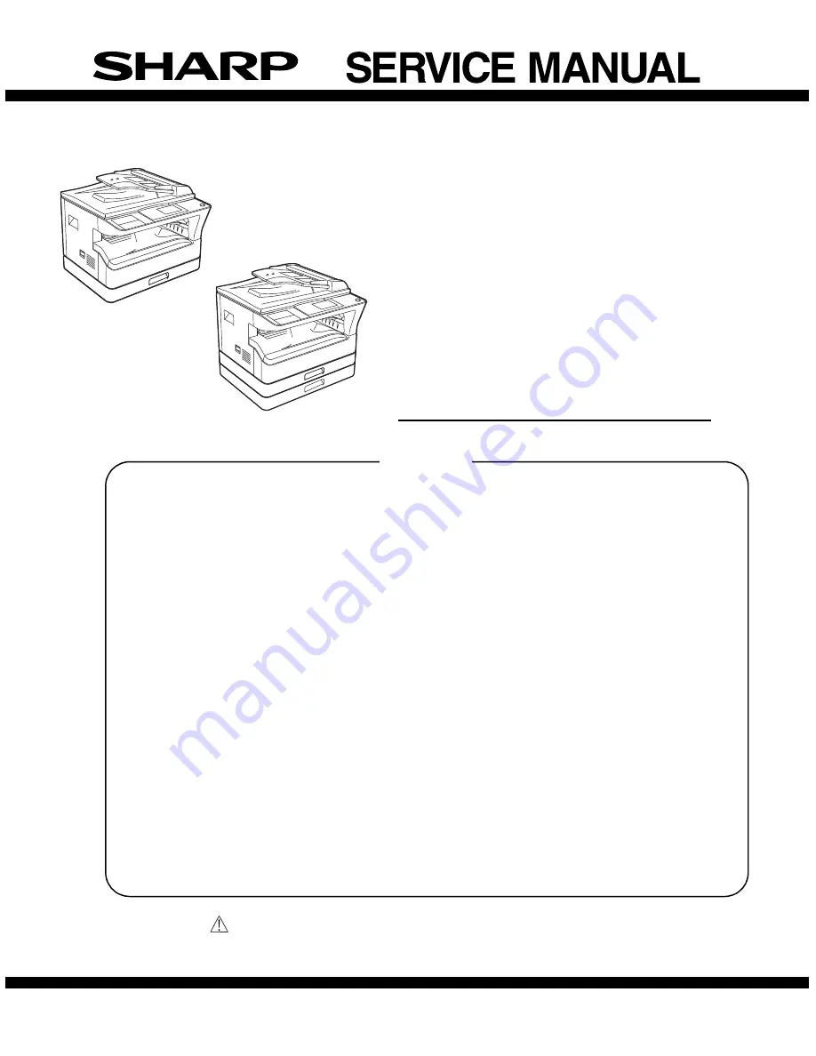
DIGITAL MULTIFUNCTIONAL 
SYSTEM

MX-M182

MX-M182D

MX-M202D

MX-M232D

CODE : 00ZMXM182/S1E

MX-M182/M182D

MX-M202D/M232D

(With optional 

SPF/RSPF installed)

(With optional 

SPF/RSPF installed)

[ 1 ] GENERAL . . . . . . . . . . . . . . . . . . . . . . . . . . . . . . . . . . . . . . . . . 1 - 1

[ 2 ] CONFIGURATION . . . . . . . . . . . . . . . . . . . . . . . . . . . . . . . . . . . 2 - 1

[ 3 ] SPECIFICATIONS . . . . . . . . . . . . . . . . . . . . . . . . . . . . . . . . . . . 3 - 1

[ 4 ] CONSUMABLE PARTS . . . . . . . . . . . . . . . . . . . . . . . . . . . . . . . 4 - 1

[ 5 ] EXTERNAL VIEWS AND INTERNAL STRUCTURES  . . . . . . . 5 - 1

[ 6 ] ADJUSTMENTS  . . . . . . . . . . . . . . . . . . . . . . . . . . . . . . . . . . . . 6 - 1

[ 7 ] SIMULATIONS. . . . . . . . . . . . . . . . . . . . . . . . . . . . . . . . . . . . . . 7 - 1

[ 8 ] TROUBLE CODE LIST . . . . . . . . . . . . . . . . . . . . . . . . . . . . . . . 8 - 1

[ 9 ] MAINTENANCE  . . . . . . . . . . . . . . . . . . . . . . . . . . . . . . . . . . . . 9 - 1

[10] DISASSEMBLY AND ASSEMBLY . . . . . . . . . . . . . . . . . . . . . . 10 - 1

[11] OPERATIONAL DESCRIPTIONS . . . . . . . . . . . . . . . . . . . . . . 11 - 1

[12] FLASH ROM VERSION UP PROCEDURE. . . . . . . . . . . . . . . 12 - 1

[13] IP ADDRESS SETTING  . . . . . . . . . . . . . . . . . . . . . . . . . . . . . 13 - 1

[14] ELECTRICAL SECTION . . . . . . . . . . . . . . . . . . . . . . . . . . . . . 14 - 1

CONTENTS

MODEL

Содержание MX-M182D

Страница 1: ...IONAL SYSTEM MX M182 MX M182D MX M202D MX M232D CODE 00ZMXM182 S1E MX M182 M182D MX M202D M232D With optional SPF RSPF installed With optional SPF RSPF installed 1 GENERAL 1 1 2 CONFIGURATION 2 1 3 SPECIFICATIONS 3 1 4 CONSUMABLE PARTS 4 1 5 EXTERNAL VIEWS AND INTERNAL STRUCTURES 5 1 6 ADJUSTMENTS 6 1 7 SIMULATIONS 7 1 8 TROUBLE CODE LIST 8 1 9 MAINTENANCE 9 1 10 DISASSEMBLY AND ASSEMBLY 10 1 11 O...

Страница 2: ...Disconnect the AC cord before servicing the unit LASER WAVE LENGTH 785 15mm Pulse times 10 34 s 0 1 s 7mm MX M182 MX M182D MX M202D 8 665 s 0 1 s 7mm MX M232D Out put power Max 0 3mW ...

Страница 3: ...tion result code 8 6 9 MAINTENANCE 1 Maintenance table 9 1 2 Maintenance display system 9 2 3 Note for replacement of consumable parts 9 2 10 DISASSEMBLY AND ASSEMBLY 1 High voltage section Duplex transport section 10 1 2 Optical section 10 2 3 Fusing section 10 4 4 Paper exit section 10 7 5 MCU 10 10 6 Optical frame unit 10 10 7 LSU 10 10 8 Tray paper feed section Paper transport section 10 11 9 ...

Страница 4: ...tments or performance of procedures other than those specified herein may result in hazardous laser radiation exposure The socket outlet shall be installed near the machine and shall be easily accessible C Note for installation place Improper installation may damage the machine Please note the following during initial installation and whenever the machine is moved Caution If the machine is moved f...

Страница 5: ... static electricity 1 When in transit or storing put the parts in an anti static bag or an anti static case and do not touch them with bare hands 2 When and after removing the parts from an anti static bag case use an earth band as shown below Put an earth band to your arm and connect it to the machine 3 When repairing or replacing an electronic part perform the procedure on an anti static mat ...

Страница 6: ...X M182D MX M202D AR VR7 MX M182 is standard MX NB12 AR RP10 MX M182D M202D M232D only MX FX13 MX EB14 MX XB17 MX TR10 MX USX1 Sharpdesk 1 license kit MX PK10 PS3 EXPANSION KIT MX USX5 Sharpdesk 5 license kit MX US10 Sharpdesk 10 license kit MX US50 Sharpdesk 50 license kit MX USA0 Sharpdesk 100 license kit ...

Страница 7: ... feeder SPF O O 2 AR D36 250 sheet paper feed unit O O AR D37 2x250 sheet paper feed unit O O AR VR7 DOCUMENT COVER STD O 2 MX NB12 NETWORK EXPANSION KIT O O MX FX13 FACSIMILE EXPANSION KIT O 3 O 3 MX XB17 FACSIMILE MOUNTING KIT O O MX TR10 JOB SEPARATOR O O MX EB14 EXPANSION MEMORY BOARD O O MX PK10 PS3 EXPANSION KIT O 4 O 4 MX USX1 SHARPDESK 1 LICENSE KIT O O MX USX5 SHARPDESK 5 LICENSE KIT O O ...

Страница 8: ...2D M232D Network expansion kit MX NB12 MX M182 M182D M202D M232D Document cover AR VR7 MX M182D M202D M232D Job separator MX TR10 MX M182 M182D M202D M232D PS3 Expantion kit MX PK10 MX M182 M182D M202D M232D Facsimile expantion kit MX FX13 MX M182 M182D M202D M232D Facsimile mounting kit MX XB17 MX M182 M182D M202D M232D Expantion memory board MX EB14 MX M182 M182D M202D M232D Paper size MX M232D ...

Страница 9: ...ble Heavy paper 129 200g m2 33 6 53 2lbs N A N A Yes A4 or less Only single paper feed Heavy paper 201 256g m2 53 3 68lbs N A N A N A Envelope 75 90g m2 20 24lbs N A N A Yes Postcard N A N A Yes OHP film N A N A Yes Label sheet N A N A Yes Tab paper 20 N A N A N A Max number of multi copy 999 sheets Warm up time 25 seconds or less Pre heat Available Jam recovery Within 25 sec Fixed magnification r...

Страница 10: ...nterface only Auditor support O Supporting the interface only Duplex X O Toner save O Set according to the destination Account control O Copy Printer Scanner Number of control 50 Photoconductor type OPC Organic Photo Conductor Photoconductor drum dia 30mm Copy lamp WhiteCCFL Developing system Dry 2 component magnetic brush development Charging system Saw teeth charging Transfer system DC corotron ...

Страница 11: ...collate If Collate is specified plural printing by the number of set is done and Uncollate is specified plural printing by page is done Document Style 1 sided 2 sided Book 2 sided Tablet Simplex or duplex printing is done depending on the setting Print direction is different depending on book tablet for duplex printing Simplex model have no duplex function N up 2 4 6 Specified numbers of pages are...

Страница 12: ...density compatibility 1 5 stages Default 3 Duplex print Compatibility Yes No Specify duplex printing function with giving priority to driver Duplex Style compatibility Pattern1 Pattern2 Pattern3 Default 1 Print by number of copy compatibility Yes No Specify print by set function with giving priority to driver Water marks Watermark None TOP SECRET CONFIDENTIAL DRAFT ORIGINAL COPY Select watermark s...

Страница 13: ...eft Center N A XY Zoom N A Width 25 400 Length 25 400 Lock Aspect Ratio On Off Reference Point Upper left Center Fit to Page size A3 B4 A4 B5 A5 B6 A6 11x17 8 5x14 8 5 x 13 4 8 5x13 8 5x11 5 5x8 5 Folio Executive COM 10 DL C5 8K 16K A3 B4 A4 B5 A5 B6 A6 11x17 8 5x14 8 5 x 13 4 8 5x13 8 5x11 5 5x8 5 Folio Executive COM 10 DL C5 8K 16K Paper Selection Auto Bypass Auto Bypass Manual Tray 1 2 3 4 Auto...

Страница 14: ...le On First Page only Yes No Yes No Special Mode Page Interleave Yes N A Paper Insertion Setting Different 1st Cover and Last Page 1st Page On Off Last Page Not Support 1st Page On Off Last Page Not Support Duplex Printing Yes No Yes No Paper Tray Bypass Auto Bypass Manual Tray 1 2 3 4 Bypass Auto Bypass Manual Tray 1 2 3 4 Transparency Inserts N A N A Carbon Copy N A N A Option ROPM On Off On Off...

Страница 15: ...it To Page Custom 1 Output Tray Upper Tray Center Tray Upper Tray Center Tray Mode Sub Mode Scanner E mail Yes MX NB12 is expanded FTP Server Network Folder SMB No Desktop Yes MX NB12 is expanded USB Memory Twain Scan Including Button Manager Yes Mode Mode Type Support Scanner MX NB12 is expanded File Format B W TIFF Yes PDF Yes PDF A N A Encrypted PDF N A XPS N A File Format Gray Scale TIFF Yes J...

Страница 16: ... Available Lead Edge Trail Edge 2 5mm Right Left 3 0mm Storing of Setting Contents Yes Keeping of Preview Image Yes Unit of Display for Scanning Range Pixel mm inch Notes Security Feature No Support OS Windows 2000 Professional Windows XP Home Edition Windows XP Professional Windows Vista Windows 7 Scan Resolution 75x75 100x100 150x150 200x200 300x300 400x400 600x600dpi main direction x sub direct...

Страница 17: ...ral pages file Default All pages file Resolution Resolution 75dpi 100dpi 150dpi 200dpi 300dpi 400dpi 600dpi Set the output resolution Default 150dpi Duplex 1 side 2 sided original 1 side 2 sided Set the original type whether 1 side or 2 sided This menu will appear when RSPF is installed If 2 sided is specified original is scanned only by RSPF Default 1 side Vertical original set vertical Horizonta...

Страница 18: ...nyl bag x1 x1 16K Life setting by A4 6 document 2 Developer MX 235GV Developer x1 50K 3 Drum KIT AR 205DM Drum Drum fixing plate x1 x1 50K No Name Product name Content Life Remarke 1 Toner cartridge Black MX 235GT Toner cartridge Vinyl bag x1 x1 16K Life setting by A4 6 document 2 Developer MX 235GV Developer x1 50K 3 Drum KIT AR 205DM Drum Drum fixing plate x1 x1 50K No Name Product name Content ...

Страница 19: ...loper toner 24 months from the production month No Name Product name Content Life Remark 1 Toner cartridge Black MX 235AT Toner cartridge Vinyl bag x1 x1 16K Life setting by A4 6 document 2 Toner cartridge Black MX 236AT Toner cartridge Vinyl bag x1 x1 8 4K Life setting by A4 6 document 3 Developer MX 235AV Developer x1 50K 4 Drum KIT AR 205DR Drum Drum fixing plate x1 x1 50K Temperature Humidity ...

Страница 20: ...he front side Ver No Production place Serial number Year Month Day 1 2 3 4 5 6 7 8 9 10 1 Number For this model this digit is 2 2 Alphabet Indicates the model conformity code G for this model 3 Number Indicates the end digit of the production year 4 Number or X Y Z Indicates the production month X stands for October Y November and Z December 5 6 Number Indicates the day of the production date 7 Nu...

Страница 21: ...led and print jobs are delivered to this tray 9 Operation panel Contains operation keys and indicator lights 10 Front cover Open to remove paper misfeeds or replace the toner cartridge 11 Tray 1 Tray 1 can hold approximately 250 sheets of copy paper 80 g m2 20 lbs 12 Tray 2 Tray 2 can hold approximately 250 sheets of copy paper 80 g m2 20 lbs 13 Document cover when installed Open to make a copy fr...

Страница 22: ...ce the original s that you wish to scan face up here Up to 40 sheets can be placed 22 Original guides when the SPF RSPF is installed Adjust to the size of the originals 23 Feeding roller cover when the SPF RSPF is installed Open to remove misfeed originals 24 Right side cover when the SPF RSPF is installed Open to remove misfeed originals 25 Fusing unit release levers To remove the paper misfeed i...

Страница 23: ...number of copies appears During copying this shows the remaining number of copies 9 OK key Press to enter the selected setting 10 Numeric keys Use to select the number of copies 11 C key Press to clear the set number of copies or stop a copy run 12 INTERRUPT key INTERRUPT indicator Interrupts a copy run to allow an interrupt copy job to be performed 13 FAX key indicator when the fax option is inst...

Страница 24: ...k up roller 6 PS clutch RRC Drives the resist roller 7 Bypass tray paper transport clutch MPTC Drives the bypass tray paper transport roller 8 Bypass tray paper feed solenoid MPFS Bypass tray paper feed solenoid 9 2nd tray transport clutch FSCL1 Drives the 2nd tray transport roller MX M202D M232D 10 2nd tray paper feed clutch PSCL2 Drives the 2nd tray paper feed roller MX M202D M232D 11 Exhaust fa...

Страница 25: ...ED Bypass tray transport detection 10 2nd tray door open close sensor DRS2 2nd tray door open close detection MX M202D M232D 11 2nd tray door paper pass sensor PPD2 2nd tray paper entry detection MX M202D M232D 12 2nd tray paper empty sensor CSS2 2nd tray paper empty detection MX M202D M232D 13 Paper in sensor PIN Paper transport detection 14 Tray empty CSS1 Tray paper entry detection 15 Front cov...

Страница 26: ...mage scanning 3 Main control PWB Main control PWB 4 2nd tray PWB 2nd tray control 5 High voltage PWB High voltage control 6 Power PWB AC power input DC power control 7 Operation main PWB Operation panel input Display operation panel section control 8 USB I F PWB Connect a USB device 9 LCD OPE PWB Display and operation panel control 1 7 9 6 5 3 4 2 8 ...

Страница 27: ...rubber roller 10 Waste toner transport roller Transports waste toner to the waste toner box 11 Drum unit Forms images 12 Transfer charger unit Transfer images on the drum onto paper 13 DUP follower roller Transports paper for duplex 14 Duplex transport roller Transports paper for duplex 15 Resist roller Takes synchronization between the paper lead edge and the image lead edge 16 Bypass tray Bypass...

Страница 28: ...sure the distance from the marking position to the top of the doctor plate of the developing unit to insure that it is 18mm If the distance is not within the specified range loosen the fixing screw A of the main pole adjustment plate and move the adjustment plate in the arrow direction to adjust Section Adjustment item Adjustment procedure SIM No A Process section 1 Developing doctor gap adjustmen...

Страница 29: ... the copy output If necessary perform the following adjustment procedures 4 Execute SIM 50 01 Select a desired mode with the arrow keys enter the adjustment value with 10 key and press OK key When START key is pressed a sheet is printed Adjustment specification 5 Set the OC lead edge position set value RRC A to 1 The OC image scanning start position is shifted inside the document edge 6 Set the ma...

Страница 30: ... step of the set value corresponds to about 0 1mm shift Calculate the set value from the formula below B 0 05 mm Lead edge void adjustment value B Lead edge void mm Example When setting the lead edge void to 2 5mm 2 5 0 05 about 50 Note If the set value is not obtained from the above formula perform the fine adjustment b SPF image lead edge position adjustment SIM50 6 1 Set a scale on the OC table...

Страница 31: ... a paper feed port and make a copy Compare the copy and the test chart If necessary perform the following adjustment procedure 3 Execute SIM 26 43 and set the density mode to SIDE VOID L SIDE VOID R The currently set adjustment value is displayed 4 Enter the set value and press the start key The correction value is stored Adjustment specification Adjustment mode SIM Display text array Set value Sp...

Страница 32: ...se unit parallelism is proper If one of them is in contact with the positioning plate perform the adjustment of 4 4 Loosen the set screw of the scanner drive pulley which is not in contact with No 2 3 mirror base unit positioning plate 5 Without moving the scanner drive pulley shaft manually turn the scanner drive pulley until the positioning plate is brought into contact with No 2 3 mirror base u...

Страница 33: ...n adjustment When there is no skew copy in the mirror base scanning direction and there is no horizontal error right angle to the scanning direction the adjustment can be made by adjusting the No 2 3 mirror base unit rail height Before performing this adjustment be sure to perform the horizontal image distortion adjustment in the laser scanner section This adjustment must be performed in the follo...

Страница 34: ...e or original glass Be careful to avoid this 5 Main scanning direction FR direction magnification ratio adjustment SIM 48 1 Note Before performing this adjustment be sure to check that the CCD unit is properly installed 1 Put a scale on the original table as shown below 2 Execute SIM 48 1 3 After completion of warming up shading is operated and the current correction value of the main scanning dir...

Страница 35: ...e image and the actual image If necessary perform the following adjustment procedures 4 Execute SIM 48 5 5 After warm up shading is performed 6 Check to confirm that the RSPF SIDE1 mode is selected with the cross cursor 7 Enter the set value and press the start key The set value is stored and a copy is made Adjustment specification RSPF SIDE2 is displayed only when the RSPF is installed 7 Off cent...

Страница 36: ...fication below is satisfied Adjustment specification Adjustment mode SIM Display text array Set value Specifi cations Set range Document off center OC mode 50 12 OC 1 Shifted to R side by 0 mm 1 Shifted to L side by 0 1mm Center 2 0 1 99 Sim50 12 ORG CENTER 1 OC 2 SPF SIDE1 3 SPF SIDE2 1 99 50 50 50 50 Density mode Display text array Expo sure level Sharp Gray Chart output Set value Set range Auto...

Страница 37: ...14 Trouble cancel except for U2 16 U2 trouble cancel 20 01 Maintenance counter clear 21 01 Maintenance cycle setting 22 01 Counters display 03 Jam memory display 04 Jam total counter display 07 System setting code display 09 Paper feed counter display 11 FAX related counter display 13 CRUM destination display 5 14 P ROM version display 15 Trouble memory display 22 SPF RSPF jam counter display 2 24...

Страница 38: ...E adjustment 48 01 Main sub scanning magnification ratio adjustment 05 SPF RSPF mode sub scanning magnification ratio adjustment in copying 2 08 FAX magnification ratio adjustment scan 09 FAX magnification ratio adjustment print 49 01 Flash ROM program writing mode MCU 02 Flash ROM program writing mode NNB 50 01 Image lead edge adjustment 06 Copy lead edge position adjustment SPF RSPF 2 8 FAX lead...

Страница 39: ...en in simulation The copy lamp is lighted during scanning CA key Exits the simulation mode INTERRUPT key Returns to the sub code input window C key Input value clear Numeric keys Input of the number of scanning 02 Mirror home positions sensor MHPS status display Used to monitor the mirror home position sensor and display the ON OF status of the sensor on the LCD CA key Exits the simulation mode IN...

Страница 40: ...pped and the machine returns to the sub code input window Only when the SPF RSPF is installed Main code Sub code Contents Remark Sim2 1 SPF AGING 115 100 86 1SIDE 2SIDE OK key or START Key Magnification ratio selection window ZOOM 100 EXEC Sim2 1 SPF AGING 115 100 86 1SIDE 2SIDE Execution window ZOOM 100 EXEC Select the scan magnification ratio drive speed This also accords with the magnification ...

Страница 41: ...of OFF After completion of the process the machine returns to the sub code input window When INTERRUPT key is pressed the machine returns to the sub code input window When CA key is pressed the machine exits the simulation mode Only when the SPF RSPF is installed 03 02 Shifter job separator sensor status display Used to monitor the sensors related to the shifter and the job separator and display t...

Страница 42: ...on before terminating the simulation similarly to the shifter Only when the job separator is installed 11 Shifter home position check Used to check the operations of the shifter HP sensor and the shifter When this simulation is executed the initial menu is displayed By the following key operations the left operation and the right operation of the home position sensor and the shifter can be execute...

Страница 43: ... panel are properly detected When the machine enters the key input check mode the initial menu is displayed When any key is pressed the value on the right lower side is counted up If a key is pressed once it is not counted again When CA key is pressed for the first time it is counted When it is pressed for the second time the simulation mode is terminated When INTERRUPT key is pressed for the firs...

Страница 44: ...ON of 500ms and OFF of 500ms 20 times When the operation is completed the machine returns to the sub code input window When INTERRUPT key is pressed the machine returns to the sub code input window When CA key is pressed the machine exits the simulation mode Main code Sub code Contents Remark Sim5 2 HT LAMP PRESS OK KEY EXEC Sim5 2 HT LAMP EXEC OK key or START Key Initial window Execution window S...

Страница 45: ...ulation is executed the following warm up window is displayed The time required for starting the warm up and completing the initializing operation and shifting to the stand by state is displayed Though CA key is pressed the machine does not enter the aging mode of intermission 0 sec Press CA key to exit the simulation mode The aging function is omitted from SIM 07 01 Note Toner supply operation is...

Страница 46: ...s simulation is executed the machine shifts to the following mode select window and the list of the modes to be outputted is displayed Select an output mode with numeric keys and press OK key or START key and the transfer charger output is made for about 30sec in the specified mode The items of back is not displayed when DUPLEX setting is OFF Small size paper is Letter R A4R width or below When an...

Страница 47: ...e INTERRUPT key Shift to the sub code input window Default 4 05 Duplex motor switchback time adjustment Used to adjust the duplex motor switchback time when the motor reverse rotation is controlled When this simulation is executed the following setting window is displayed Enter an input value with numeric keys and press OK key or START key The setting range is 50 76 When the adjustment value is in...

Страница 48: ...tenance counter clear Used to clear the maintenance counter Press OK key or START key on the following window the maintenance counter is cleared and the machine returns to the sub code input window 21 01 Maintenance cycle setting Used to set the maintenance cycle When this simulation is executed the current set value is displayed Enter a desired code with numeric keys and press START key The set v...

Страница 49: ...nnn DUPLEX nnnnnnn OTHERS nnnnnnn MNTCYC nnnnnnn Sim22 1 COUNTER 4 4 DEV TTL nnnnnnn DRM TTL nnnnnnn Counter display TOTAL Total counter MAINTE Maintenance counter DEV Development counter DRUM Drum counter CPY JOB Copy job counter PRT JOB Print job counter SCN JOB Scan job counter OC SCN OC scan counter SPF SPF RSPF counter DUPLEX DUPLEX counter OTHERS Other counter MNTCYC Maintenance cycle DEV TT...

Страница 50: ...oard which is not installed is not displayed Main code Sub code Contents Remark Sim22 7 SYSTEM SYS CODE nnnnn Sim22 9 COUNTER 1 2 BYPASS nnnnnnn TRAY1 nnnnnnn TRAY2 nnnnnnn TRAY3 nnnnnnn Sim22 9 COUNTER 2 2 TRAY4 nnnnnnn key key Sim22 11 FAX COUN COMM PAGE SND xx xxx xxx RCV xx xxx xxx Sim22 11 FAX COUN SELECT COUNTER 3 PRINT PAGE 1 3 Sim22 11 FAX COUN COMM TIME SND hhhhhhhh mm ss RCV hhhhhhhh mm ...

Страница 51: ... and the jam memory are cleared and the machine shifts to the sub code input window 02 Trouble memory clear Used to clear the trouble memory and the trouble history data in the EEPROM When INTERRUPT key is pressed the machine shifts to the sub code input window When CA key is pressed the machine exits the simulation mode Only when the SPF RSPF is installed 04 SPF RSPF counter clear Used to clear t...

Страница 52: ...nter clear Used to clear the printer counter and other counters Select a counter to be cleared and press OK key or START key The confirmation window is displayed Press OK key or START key again and the specified counter is cleared and the machine returns to the initial window CA key Exits the simulation mode INTERRUPT key Shifts to the sub code input window Main code Sub code Contents Remark Sim24...

Страница 53: ...K key or START key Clears the scanner mode counter and shifts to the sub code input window CA key Exits the simulation mode INTERRUPT key Shifts to the sub code input window Main code Sub code Contents Remark SEND PAGE xx xxx xxx TIME hhhhhhhh mm ss EXEC CLEAR FAX COUNTER 3 PRINT PAGE 1 3 X Sim24 10 CLR COUN RECEIVE PAGE xx xxx xxx TIME hhhhhhhh mm ss EXEC Sim24 10 CLR COUN CLEAR FAX COUNTER 1 SEN...

Страница 54: ...Close the side cover Start LED ON 5 Press OK key or START key When OK key or START key is pressed the main motor rotates for 3 minutes to determine the toner sensor reference value and clear the developer rotation time in addition the developer counter is cleared When the procedures are completed normally the ATC sensor reference value is displayed on the value display section In case of an error ...

Страница 55: ...able of FC 8 5 x 13 size detection and mexican legal size detection Detection size when FC 8 5 x 13 size and mexican legal size document is used For destinations other than the above this setting is invalid Main code Sub code Contents Remark Sim25 10 LSU CHECK PRESS OK KEY EXEC Sim25 10 LSU CHECK EXEC OK key or START Key Execution start window Execution window Sim26 1 JBS SET 1 JOB SEPARATOR 0 NON...

Страница 56: ...ally resulting in a paper jam Default 0 MX M182 1 MX M182D MX M202D MX M232D 05 Count mode setting Used to set the count up number of the total counter the developer counter and the maintenance counter individually when a special paper A3 WLT 8K is passed When this simulation is executed the current set value is displayed 1 3 Enter a value with numeric keys and press OK key or START key to save th...

Страница 57: ...code input window 08 Manual transfer shaking countermeasures setting Used to set the countermeasures against manual transfer shaking When this simulation is executed the current set value is displayed Enter a set value with numeric keys and press OK key or START key The set value is saved in the EEPROM CA key Exits the simulation mode INTERRUPT key Shifts to the sub code input window 18 Toner save...

Страница 58: ...conformity control ON OFF Used to set Yes No of CE mark conformity When this simulation is executed the current set value is displayed Enter a value with numeric keys and press OK key or START key The set value is saved to EEPROM and the machine returns to the sub code input window CA key Exits the simulation mode INTERRUPT key Shifts to the sub code input window Default 0 100V series 1 200V serie...

Страница 59: ...n the developer counter reaches the life over CA key Exits the simulation mode INTERRUPT key Shifts to the sub code entry menu Default 1 39 Memory capacity check Used to check the capacity of the image memory SDRAM installed to the MCU PWB and the capacity of the IMC compression memory There are two kinds of the displayed image memory capacity 16MB and 32MB The standard capacity of the IMC compres...

Страница 60: ... increased by 0 5mm The default is 5 2 5mm Display Set item 1 SIDE BOID L Left side void amount setting 2 SIDE VOID R Right side void amount setting CA key Exits the simulation mode INTERRUPT key Shifts to the sub code input window Default 5 Void amount 2 5mm Main code Sub code Contents Remark Item selection Sim26 42 TC TIMING Sim26 42 TC TIMING Sim26 42 TC TIMING 2 1 TC ON 2 TC OFF 1 99 38 50 50 ...

Страница 61: ...TART key is pressed the setting is saved to the EEPROM CA key Exits the simulation mode INTERRUPT key Shifts to the sub code input window Default 1 1 2 1 3 1 4 1 5 1 6 1 7 1 8 1 60 FAX key Enable Disable setting Used to set Enable Disable of the FAX key when the FAX PWB is not installed Though this setting is set to Enable if the FAX PWB is not installed a message of FAX PWB is not installed is di...

Страница 62: ...ts to the sub code input window Default 0 30 01 Paper sensor status display Used to display the list of paper sensor status on the LCD An active sensor is highlighted The display items and corresponding sensors are shown below When a multi stage cassette is not installed as an option the corresponding sensor name is not displayed Main code Sub code Contents Remark Code number Setting contents 0 To...

Страница 63: ...splay The values in parentheses of sensor 4 and 5 are the threshold values of adjustment at SIM41 04 Since sensors 1 and 3 are not provide with the threshold value of detection at SIM41 04 0 is always displayed 04 Detection level adjustment when the document size is settled 15 degrees 20 degrees Set the OC cover to the document size settled state 15 degrees 20 degrees and press OK key The detectio...

Страница 64: ...re when starting main motor preliminary rotation 80 160 4 5 MOTOROFF Main motor preliminary rotation end time sec 0 90 6 WUPEND Warm up compulsory termination time sec 0 90 1 When the set value is increased by 1 the target temperature is increased by 5 C Refer to Table 1 2 When the set value is increased by 1 the target temperature is increased by 10 C Refer to Table 2 3 When the set value is incr...

Страница 65: ...decreased For the set value refer to Table 1 and 2 Enter a desired set value temperature and press OK key or START key The set value is caved in the EEPROM Window display Setting item Setting range 1 PREHEAT Main thermistor target temperature during preliminary heating 80 160 1 2 WARMUP1 When the initial temperature is below 120 C during warm up 150 230 2 Main thermistor target temperature 3 WARMU...

Страница 66: ...re is increased by 5 C Refer to Table 3 3 Correction temperature from starting a JOB to reaching the JOB initial temperature correction number of sheets 4 Correction temperature from the JOB initial temperature correction number of sheets to JOB end Table 3 CA key Exits the simulation mode INTERRUPT key Shifts to the sub code input window Default TMPFIRST 5 TMPLAST 5 CNTFIRST 3 CNTTYPE1 50 CNTTYPE...

Страница 67: ... Purge process are simulations for analysis do not set them to 1 Enable If they are set to 1 Enable the toner density rises or falls abnormally and developer failure or toner dispersion occurs If they are set to 1 Enable erroneously developer must be replaced and the inside of the machine and the process unit must be cleaned Unconditional toner supply When the developing unit and the drum unit are...

Страница 68: ...f the setting items and the current set value are displayed Select an item to be changed with key and key and enter the adjustment value with numeric keys The setting range is 1 99 When key or key is pressed the page is changed Enter the adjustment value with numeric keys and press OK key The entered value is saved in the EEPROM and the machine shifts to the copy window Sample copying can be perfo...

Страница 69: ...lue on the example 50 is not the default value Main code Sub code Contents Remark Sim46 10 TEXT 600 19 TS 5 0 SHIFT 20 TS 5 0 GAMMA 7 7 1 99 50 50 50 Sim46 10 TEXT 600 10 5 0 GAMMA 11 TS 1 0 SHIFT 12 TS 1 0 GAMMA 4 7 1 99 50 50 50 50 Sim46 10 TEXT 600 4 2 0 GAMMA 5 3 0 SHIFT 6 3 0 GAMMA 2 7 1 99 50 50 50 50 Sim46 10 TEXT 600 13 TS 2 0 SHIFT 14 TS 2 0 GAMMA 15 TS 3 0 SHIFT 5 7 1 99 50 50 50 50 Sim4...

Страница 70: ...ity 1 shift amount 2 1 0 GAMMA PHOTO Error diffusion density 1 gamma value 3 ED 2 0 SHIFT PHOTO Error diffusion density 2 shift amount 4 ED 2 0 GAMMA PHOTO Error diffusion density 2 gamma value 5 ED 3 0 SHIFT PHOTO Error diffusion density 3 shift amount 6 ED 3 0 GAMMA PHOTO Error diffusion density 3 gamma value 7 ED 4 0 SHIFT PHOTO Error diffusion density 4 shift amount 8 ED 4 0 GAMMA PHOTO Error ...

Страница 71: ... Sim46 14 EXP LEVEL Sim46 14 EXP LEVEL After input 1 4 After input 0 99 OK key Sim46 14 EXP LEVEL Sim46 14 EXP LEVEL Sim46 14 EXP LEVEL FINE 1 AE PHOTO ON 2 AE PHOTO OFF 1㧙4 X FINE XX AE PHOTO ON 2DIGITS YY OK key FINE YY AE PHOTO ON EXEC FINE YY AE PHOTO ON SCAN EXEC FINE YY AE PHOTO ON PRINT EXEC Sim46 14 EXP LEVEL FINE 3 MANUAL PHOTO ON 4 MANUAL PHOTO OFF 1㧙4 X Sim46 13 EXP LEVEL Sim46 13 EXP L...

Страница 72: ... two modes Default 2 Main code Sub code Contents Remark OK key OK key OK key OK key Sim46 15 2 8 Sim46 15 2 8 Sim46 15 2 8 Sim46 15 2 8 Sim46 15 2 8 S FINE 1 AE PHOTO ON 2 AE PHOTO OFF 1㧙 X S FINE XX AE PHOTO ON 2DIGITS YY S FINE YY AE PHOTO ON EXEC S FINE YY AE PHOTO ON SCAN EXEC S FINE YY AE PHOTO ON PRINT EXEC Sim46 15 2 8 S FINE 3 MANUAL PHOTO ON 4 MANUAL PHOTO OFF 1㧙 X After input 1 4 After i...

Страница 73: ...he image contrast for each mode When this simulation is executed the current set value of each mode is displayed in two digits Default 50 Select an adjustment item mode with the arrow keys and enter a desired value with numeric keys When OK key is pressed the entered value is saved to the EEPROM and the machine shifts to the copy execution window After completion of copying the machine returns to ...

Страница 74: ...e is saved to the EEPROM and the machine shifts to the copy execution window After completion of copying the machine returns to the adjustment value input window When START key is pressed instead of OK key the machine shifts to the copy execution window and performs copying Default AE 1 TEXT 1 PHOTO1 1 PHOTO2 1 TEXT TS 1 AE TS 1 Main code Sub code Contents Remark Sim46 30 AE LIMIT 1 AE 2 AE TS 0 2...

Страница 75: ...MAGE Sim46 39 FAX IMAGE 1 7 input 0 2 input OK key OK key BACK key BACK key OK key Sim46 39 FAX IMAGE Sim46 39 FAX IMAGE Sim46 39 FAX IMAGE 1 STD 1 2 FINE 1 3 S FINE 1 1 7 X STD X 0 2 Y STD Y EXEC STD Y SCAN EXEC STD Y PRINT EXEC Sim46 39 FAX IMAGE 4 U FINE 1 5 FINE HT 1 6 S FINE HT 1 1 7 X Sim46 39 FAX IMAGE 7 U FINE HT 1 1 7 X The current set value of each resolution is displayed Specify a resol...

Страница 76: ...rint the document 09 FAX magnification ratio adjustment print Used to adjust and set the FAX print magnification ratio and scan and print the document Main code Sub code Contents Remark Sim48 5 R SPF ZOOM 1 RSPF SIDE1 2 RSPF SIDE2 1 99 50 50 50 Adjustment item selection window Display text array Adjustment mode 1 RSPF SIDE1 SPF RSPF sub scan direction magnification ratio adjustment on the front of...

Страница 77: ...e power ɢError MCU FAX PNL MCU PANEL 0xFF No process No process 0x00 OK OK 0x03 Data receive error Protocol error 2 Flash Rom write error Program section 0x04 Loader transfer error Flash Rom write error Common window data 0x05 Flash Rom delete error Boot Flash Rom write error Copy window data 0x06 Flash Rom delete error Program Flash Rom write error Scan window data 0x07 Flash Rom write error Boot...

Страница 78: ...r 0x06 MAIN no file 0x62 BOOT work sum check error 0x07 FONT download impossible 0x63 BOOT Flash erase error 0x08 Option FLASH connection error 0x64 BOOT Flash write error 0x09 Option FLASH no match 0x65 BOOT Flash sum check error 0x11 LOADER data size error 0x71 MAIN data size error 0x12 LOADER work sum check error 0x72 MAIN work sum check error 0x21 BOOT data size error 0x73 MAIN Flash erase err...

Страница 79: ...rt position TRAY1 is changed the print start positions TRAY2 TRAY4 and the print start position MULTI BYPASS are also changed accordingly The adjustment value is in the range of 1 99 Select an adjustment item mode with the arrow keys and enter the set value with numeric keys When OK key is pressed the entered value is saved to the EEPROM and the machine shifts to the copy execution window After co...

Страница 80: ...scanning start position is increased by 1 the scanning timing is advanced resulting in a smaller image loss Select an adjustment item mode with the arrow keys and enter a desired value with numeric keys When OK key is pressed the entered value is saved to the EEPROM and the machine shifts to the copy execution window After completion of copying the machine returns to the adjustment value input win...

Страница 81: ...about 0 1mm Select an adjustment item mode with the arrow keys and enter the set value with numeric keys Default TRAY1 50 TRAY2 50 TRAY3 50 TRAY4 50 BYPASS 50 DUPLEX 50 Main code Sub code Contents Remark Sim50 8 SCAN EDGE Sim50 8 SCAN EDGE OK key OK key OK key Sim50 8 SCAN EDGE Sim50 8 SCAN EDGE Sim50 8 SCAN EDGE Sim50 8 SCAN EDGE 1 OC 2 SPF 3 RSPF 1 3 X OC 1 LEAD EDGE XX 2 LEFT EDGE XX 1 4 X LEAD...

Страница 82: ...m mode with the arrow keys and enter the set value with numeric keys When OK key is pressed the entered value is saved to the EEPROM and the machine shifts to the copy execution window After completion of copying the machine returns to the adjustment value input window When START key is pressed instead of OK key the machine shifts to the copy execution window and performs copying Default OC 50 SPF...

Страница 83: ...d by changing the scanning end position with the simulation adjusting the image lead edge position Select an adjustment item mode with the arrow keys and enter the set value with numeric keys When OK key is pressed the entered value is saved to the EEPROM and the machine shifts to the copy execution window After completion of copying the machine returns to the adjustment value input window When ST...

Страница 84: ... 50 RSPF A5 50 DUPLEX 50 PRE FEED 32 Main code Sub code Contents Remark Sim50 19 DUP R VOID 1 PRV SIDE1 2 PRV SIDE2 3 RRC D 1 99 50 50 50 50 Adjustment item selection window Display text array Adjustment mode 1 PRV SIDE1 Paper rear edge void amount 1st print surface 2 PRV SIDE2 Paper rear edge void amount 2nd print surface 3 RRC D Print start position 2nd print surface Ready to copy S 100 8 1 2 11...

Страница 85: ... RSPF stop position of the mirror unit in the SPF RSPF copy The scanning position is basically determined by the automatic adjustment It can be also adjusted manually Default 50 Main code Sub code Contents Remark Ready to copy S 100 8 1 2 11 Copy start window Copies in progress S 100 8 1 2 11 Copy execution window Adjustment item selection window Copy start window Copy execution window End of copy...

Страница 86: ...ata update cycle is about 1sec 5 After passing 10sec the machine returns to the sub code input window 64 01 Self print Used to perform printing of one page disregarding the optical system status Also when the print command is issued from the host printing is performed When this simulation is executed warm up is performed and the ready lamp is lighted Since however the optical system is invalid ini...

Страница 87: ...X soft SW setting Used to display the FAX related soft SW on the LCD and set and change the soft SW setting with numeric keys input Main code Sub code Contents Remark Ready to copy S 100 8 1 2 11 Initial window Copies in progress S 100 8 1 2 11 OK Key or START Key After completion of printing one sheet 1 7SEG LED Sim65 10 KEY TIME 1 KEY ACK TIME 0 1 1 1 Display Setting 0 Disable 1 Enable Sim65 11 ...

Страница 88: ...001 Middle east 11111101 India 01010011 Sweden 10100101 New Zealand 01111110 Spain 10100000 Portugal 10001011 Italy 01011001 Switzerland 10100110 Finland 00111100 Denmark 00110001 Norway 10000010 Netherlands 01111011 Luxembourg 01101001 Belgium 00001111 South Africa 10011111 Czech 00101110 Slovakia 11111100 Hungary 01010001 Greece 01000110 Pohland 10001010 Russia 10111000 Brazil 00010110 Selection...

Страница 89: ...key 33600bps V34 1 MAX 2 SOFT SW 1 2 X 33600bps V34 0dB EXEC 33600bps V34 PRESS BACK TO STOP EXEC Sim66 4 SIGNAL OUT 34 DPMAKE 35 DPBREAK 1 35 XX After pressing OK key SIM66 4 initial window CA key Simulation cancel INTERRUPT key Sub code input window C key Input clear key Page select Numeric keys Number input and item selection OK key Input value settlement and execution START key Input value set...

Страница 90: ...AGE CLR CLEARED Power source OFF ON Simulation code input window Completion of execution Highlighted during execution Completion of execution Highlighted during execution After pressing OK key during execution With prints Without prints CA key Simulation cancel INTERRUPT key Sub code input window OK key Settlement BACK key Simulation code input window START key Settlement C key Disable BACK key Si...

Страница 91: ...0 or to the soft SW setting value High group of DTMF signal send level 1 Low group of DTMF signal send level Sim66 13 DIALTEST 1 PULSE 10pps 2 PULSE 20pps 3 DTMF 1 3 X Sim66 13 DIALTEST PULSE 10pps INPUT MAKE TIME YY 26 41 YY Sim66 13 DIALTEST SELECT HIGH LEVEL 1 DEFAULT 2 SOFT SW Y 1 2 X Sim66 13 DIALTEST Sim66 13 DIALTEST INPUT LOW LEVEL DTMF SOFT SW Y 0 15 XX Select with numeric keys and press ...

Страница 92: ...later SIM66 21 window 1sec later SIM66 21 window CA key Simulation cancel INTERRUPT key Sub code input window Numeric key Item selection OK key Settlement and execution START key Input value settlement and execution BACK key Returns to the selection window keys Page switch C key Disable Sim66 24 FAST CLEAR Sim66 24 FAST CLEAR OK key Sim66 24 FAST CLEAR INITIAL EXEC INITIALIZED Sim66 24 FAST CLEAR ...

Страница 93: ...elected numbers are highlighted Though numeric keys is pressed in the sequence of 1 and 5 or 5 and 1 the display is made in the sequence of the normal order 1 and 5 when OK key is pressed After pressing OK key during execution CA key Simulation cancel INTERRUPT key Sub code input window Numeric keys Item selection OK key Input value settlement and execution START key Input value settlement and exe...

Страница 94: ...Flag OFF SDT OFF DTMF OFF DETECT EXEC Sim66 33 SIGNAL CHK After selection with numeric key After pressing OK key during execution After pressing OK key during execution After pressing OK key during execution SIM66 33 initial window SIM66 33 initial window SIM66 33 initial window 1 CI FINET 2 CNG CED BT DT 3 Flag SDT DTMF CA key Simulation cancel INTERRUPT key Sub code input window C key Input clea...

Страница 95: ...aker sound volume High SW126 5 8 OK key After selection with numeric keys BACK key OK key After selection with numeric keys XX The current set value is displayed YY Input in the range of 1 Low 15 High A sound beeps at the set sound volume While the speaker is sounding EXEC is highlighted Press BACK key to stop the sound OK key Sim66 37 SPEAKER 1 RINGER 2 LINE MONITOR 3 ON HOOK 1 6 X Window display...

Страница 96: ...ode input window During execution EXEC is highlighted Incase of writing error NG is displayed After pressing OK key during execution Window display Setting range 1 CI_LEVEL_JUDGE 2 15 2 CI_CYCLE_MIN 1 254 3 CI_CYCLE_MAX 2 255 4 CI_COUNT 2 15 5 RES_3 3V_LEVEL_JUDGE 2 15 6 EXHS_LEVEL_JUDGE 2 255 Window display Setting range 7 RHS_LEVEL_JUDGE 2 15 8 SON_TIMEOUT 1 127 9 WRITE Window display Setting ra...

Страница 97: ...ommunication trouble Overrun 84 Panel board communication trouble Framing 88 Panel board communication trouble Time out 99 Panel language error CH ON None Door open CH Blink None Developing cartridge not installed Main code Sub code Details of trouble CE 00 Content General network errors Detail Other network errors Check and remedy Turn OFF and ON the power Consult the network administrator to che...

Страница 98: ...M26 39 to check to confirm that the memory capacity is 128MB If it is not 128MB replace the MCU PWB 2 If SIM26 04 is set to 1 change the setting to 0 If it is 0 replace the MCU PWB Main code Sub code Details of trouble E7 02 Content LSU trouble Detail The BD signal from the LSU cannot be detected in a certain cycle Always OFF or always ON Cause LSU connector or LSU harness defect or disconnection ...

Страница 99: ... 02 Content Copy lamp lighting abnormality Detail The copy lamp does not turn on Cause Copy lamp abnormality Copy lamp harness abnormality CCD PWB harness abnormality Check and remedy Use SIM 5 3 to check the copy lamp operations When the copy lamp lights up Check the harness and the connector between the CCD unit and the MCU PWB When the copy lamp does not light up Check the harness and the conne...

Страница 100: ...tection MAIN Detail The fusing temperature exceeds 245C Cause Thermistor abnormality Control PWB abnormality Fusing section connector disconnection Check and remedy Use SIM 5 02 to check the heater lamp blinking operation When the lamp blinks normally Check the thermistor and its harness Check the thermistor input circuit on the control PWB When the lamp keeps ON Check the power PWB and the lamp c...

Страница 101: ...etails of trouble L4 01 Content Main motor lock detection Detail The main motor does not rotate After rotation of the main motor the motor lock signal is detected for 1 sec or more During rotation of the main motor the motor lock signal is detected for 1 sec When the main motor is stopped the motor lock signal is not detected for 5sec or more Though the motor is stationary it is judged as stable r...

Страница 102: ...ine reset Power OFF ON 81 Content Panel board communication trouble Parity Detail A parity error occurs in communication between the MCU and the Panel PWB Cause MCU PWB Panel PWB harness trouble Garbled data Check and remedy MCU PWB Panel PWB harness trouble Replace the panel or the MCU PWB Machine reset Power OFF ON 82 Content Panel board communication trouble Overrun Detail An overrun error occu...

Страница 103: ...rror When a document jam occurs during direct transmission Send 46 No response from the other party When the FAX signal from the other party is not detected within T1 time Send Poll 48 OK Communication normal end 49 The other party has no polling function When the called side has no polling function in polling reception Poll When the called side has no transmission data Bulletin 50 Polling is not ...

Страница 104: ...e 69 Memory over Memory over in quick online sending Result code 2 Communication interruption content Transmission Reception 02 EOL time over Reception 03 Carrier detection time over Reception 06 Memory image decoding error Reception 07 Memory image decoding error Transmission 08 Time up between frames in phase C Transmission Reception 11 Polarity reversion detection Reception 12 Invalid command r...

Страница 105: ...n Developer X DV seal X X X X X Toner density sensor X X X X X X Check the sensor head surface DV side seal F R X X X X X X Optical section Reflector O O O O O O Mirrors O O O O O Pulley X X X X X CCD Lens O O O O O Table glass O O O O O O White Plate O O O O O O Drive wire X X X X X Rail X X X X X OC O O O O O O LSU Dust proof glass O O O O O O Paper feed section Manual feed take up roller O O O ...

Страница 106: ...ay levels 100 75 50 25 10 LO c Press the density adjustment LIGHT key to cancel Remaining quantity NEAR EMPTY About 10 EMPTY Message and icon on the LCD ON Flash Machine Operation allowed Stop Developer Life 50K Message and icon on the LCD ON at 50K of the developer count Machine Selection is available between Not Stop and Stop by Service Simulation SIM 26 37 Setup If Stop is selected the LED will...

Страница 107: ...he charger wire must be free from twists or bending Be sure to put the charger wire in the V groove C Duplex transport section No Item 1 High voltage section Duplex transport section 2 Optical section 3 Fusing section 4 Paper exit section 5 MCU 6 Optical frame unit 7 LSU 8 Tray paper feed section Paper transport section 9 Bypass tray section 10 Power section 11 Developing section 12 Process sectio...

Страница 108: ...t No 2 3 mirror unit to the positioning plate A Assembly Put the notched surface of wire holder 3 downward tighten temporarily and install Adjustment Main scanning direction distortion balance adjustment C Inverter PWB for copy lamp D Copy lamp No Content A Table glass B Copy lamp unit C Inverter PWB for copy lamp D Copy lamp E Lens unit F Wire G Document detection 1 1 2 4 3 3 4 4 3 A 1 3 2 A 2 1 ...

Страница 109: ... is loosened the position and the angle of the CCD unit base may be changed to cause a problem which cannot be adjusted in the market In that case the whole scanner unit must be replaced 5 Slide the CCD unit in the arrow direction CCD sub scanning direction to change the installing position When the copy image is longer than the original scale shift the CCD unit in the direction B When the copy im...

Страница 110: ...For AB series 3 Fusing section A Fusing unit removal 1 2 3 4 4 1 1 2 2 3 4 3 2 No Contents A Fusing unit B Thermostat C Thermistor D Heater lamp E Upper heat roller F Separation pawl G Lower heat roller H Separation pawl 2 2 2 3 1 1 3 4 3 2 3 point special screw 2 M4 x 8 2 M3 x 8 1 1 ...

Страница 111: ...ntact with heat roller Check that the thermistor is in contact with the upper heat roller D Heater lamp Assembly Insert the spring A into the hole B in the fusing frame Assembly Put the fusing harness A on the heater lamp B as shown in the figure and fix them together R Place the fusing harness inside the rib C 1 2 3 2 A 1 2 1 2 A B 3 1 3 2 1 2 1 3 2 ...

Страница 112: ... It is grease JFE552 application on a fusing frame metal plate part Degree to thinly F Separation pawl G Lower heat roller Assembly When assembling the fusing front paper guide 3 temporarily fix the paper guide fixing plate with the screw so that the paper guide fixing plate 2 is in contact with the fusing lower frame bottom A Align the edge B of the fusing front paper guide 3 with the top C of th...

Страница 113: ...ing lower frame lib H Separation pawl 4 Paper exit section A Ozone filter B Cooling fan Grease JFE552 No Content A Ozone filter B Cooling fan C Paper exit unit D Paper exit sensor duplex sensor E Transport roller F Paper exit roller G Paper exit interface PWB 1 1 2 1 1 1 2 3 ...

Страница 114: ...MX M182 DISASSEMBLY AND ASSEMBLY 10 8 C Paper exit unit A Simplex B Duplex sensor 1 2 2 3 1 1 1 2 1 1 1 1 1 3 4 1 2 3 3 5 5 1 1 3 2 1 4 4 6 5 5 1 1 3 2 1 4 4 6 ...

Страница 115: ... Paper exit roller Assembly Insert the spring pin so that the waveform A of the spring pin faces in the longitudinal direction of the paper exit drive gear long hole B Be sure to insert two ribs C into the groove D G Paper exit interface PWB 3 3 3 1 2 1 A B 1 2 1 1 2 3 4 5 3 1 1 2 A B D C C 1 1 2 2 2 3 4 4 3 3 3 1 2 1 1 2 1 3 1 ...

Страница 116: ... unit in the sequence shown above 7 LSU A LSU unit Note Do not disassemble the LSU Note When replacing the LSU be careful not to touch the dust shield glass Note Turn OFF the machine power anddisconnect the power plug from the power outlet Adjustment Image lead edge position adjustment Image left edge position adjustment Paper off center adjustment No Content A MCU disassembly No Content A Optical...

Страница 117: ...y engaged in the frame B PS clutch Resist roller C Paper feed clutch Paper feed roller D Connection gear unit No Content A Drive unit B PS clutch Resist roller C Paper feed clutch Paper feed roller D Connection gear unit 2 1 3 6 4 5 7 1 1 2 3 7 4 5 6 1 2 4 3 1 1 3 2 4 5 6 1 Apply rice grain sized grease G 484 to the front surface of the specified gear Grease G 484 for the drive section ...

Страница 118: ...installing direction of the bypass tray transport roller 6 B Bypass tray paper feed C Bypass tray solenoid When installing the solenoid shift it in the arrow direction and install No Content A Bypass tray transport roller Bypass tray paper feed roller B Bypass tray paper feed C Bypass tray solenoid D Bypass tray transport clutch E Bypass tray paper feed clutch F Pressure plate unit A A A 3 4 5 2 1...

Страница 119: ...Z E Bypass tray paper feed clutch Note Push the lever at the right edge of the multi frame cover to the right upper side and remove it F Pressure plate unit 1 2 3 Apply grease FG 40H to the gray area UKOG 0004QSZZ 1 1 2 A A A 2 2 3 1 3 1 2 4 Apply grease FG 40H to the gray area UKOG 0004QSZZ 2 1 3 2 1 3 ...

Страница 120: ... 14 10 Power section A Power unit B High voltage P W B C Power P W B D Power switch No Content A Power unit B High voltage P W B C Power P W B D Power switch 2 1 1 1 1 1 3 4 1 1 1 1 2 1 1 1 3 2 2 2 2 2 2 2 2 2 2 2 2 2 1 2 1 2 2 3 2 2 1 1 ...

Страница 121: ...e position adjustment Note Attach it to fit with the attachment reference when replacing the DV blade No Contents A Developing box B Developing doctor C MG roller 2 3 3 3 4 1 1 2 5 4 3 3 0 0 5 0 0 5 Attaching reference DV blade Mark off line Mark off line reference The DV blade surface must be free from foreign materials Do not touch the DV blade tip It must be free from deflection ...

Страница 122: ...n and remove the dirt 2 Apply KYNAR to prevent blade flip Check method Check to confirm that the OPC drum is free from fingerprints or oily dirt and that the cleaning blade is completely cleaned by the following method Make a print of a half tone image on all the surface of A4 11 x 8 5 paper and check the printed paper for any abnormality in the image 2 Prior exposure prevention Note Avoid servici...

Страница 123: ...g pin B Tray interface P W B No Contents A Operation P W B B Tray interface P W B C 2nd tray paper entry sensor Paper empty sensor D 2nd tray transport clutch E 2nd tray transport roller F 2nd tray paper feed clutch G Main motor H Paper entry sensor I Paper empty sensor 3 4 3 1 2 5 5 5 6 7 5 2 1 1 3 1 positioning pin hole 3 2 2 1 1 2 1 1 1 1 1 1 1 2 2 2 1 1 3 ...

Страница 124: ...nsor Paper empty sensor Disassembly When the second paper feed unit is detached the screw is removed and the main body is lifted D 2nd tray transport clutch E 2nd tray transport roller F 2nd tray paper feed clutch G Main motor 2 3 5 1 4 1 2 1 3 2 1 1 2 3 4 1 2 1 2 3 ...

Страница 125: ...MX M182 DISASSEMBLY AND ASSEMBLY 10 19 H Paper entry sensor I Paper empty sensor 1 1 2 3 1 2 3 ...

Страница 126: ...d a paper feed clutch does ON and a paper feed roller turns A transportation clutch does ON and the paper is sent to the transportation department By a separation plate to prevent against double feed of paper Main motor Transportation clutch Paper feed clutch Tray detection switch Paper pass sensor Transport roller Paper feed roller Separation plate Door open close sensor Paper empty sensor ...

Страница 127: ...ce Downtool 2 Download procedure 1 Main body side Executable by performing the Service Simulation No 49 01 Flash Rom program writing mode A word Download mode appears on the operation panel to denote the download mode status 2 Connect the PC and the main body with the download cable USB cable 3 PC side Boot the maintenance program Select the model icon Sample display 4 PC side Confirm that the Sim...

Страница 128: ...After the download data transmission has been completed exit the software program The USB cable can be removed at this point NOTE For making a second connection with another machine select the File and Reconnect in the menu bar on the maintenance program at the time of the USB being re connected Repeat the previous procedures from the above 5 Forbidden actions while downloading Important Failure i...

Страница 129: ...ect in the menu bar 6 PC side Confirm a tree is displayed under the Special MCU Panel Facsimile on the maintenance program If no tree is displayed confirm that the USB is connected and select the Reconnect the above 5 again 7 PC side Double click Special MCU Panel Facsimile in the main tree item to develop the sub tree items and double click Confirm version in the sub tree items 8 Check to confirm...

Страница 130: ...splayed on the maintenance program 5 PC side When the message the main body has not got started running is displayed on the lowest area of the figure below after the maintenance program is started up select the File and then Reconnect in the menu bar 6 PC side Confirm a tree is displayed under the Special MCU Panel Facsimile on the maintenance program If no tree is displayed confirm that the USB i...

Страница 131: ... FAX they will not affect the following operations 5 Updating the MX NB12 firmware A Preparation Write the firmware file with extension of brn into the MX NB12 Necessary items for updating brn Firmware USB memory Caution The firmware brn must be copied to the root directory in the USB memory in advance B Updating procedures 1 Insert the USB memory into the machine Caution Once the USB memory is in...

Страница 132: ... Include this location in the serch If the retrieval area does not include the folder which includes the maintenance tool driver Mainte inf select Browse If the folder path is properly shown press the NEXT button to go to procedure 7 5 Select the folder which includes the maintenance tool driver Mainte inf and press the OK button When the driver is included in the C Sirius folder 6 Check that the ...

Страница 133: ... press the NEXT button 6 Press the Browse button Specify the folder which includes the maintenance tool driver Mainte inf 7 Specify the folder which includes the maintenance tool driver Mainte inf and press the OPEN button Check that the path to the folder which includes the maintenance tool driver Mainte inf is properly displayed and press the OK button When the maintenance tool driver is include...

Страница 134: ...matically If the IP address changes printing will not be possible C Setting changing the ip address manually Perform the following procedure to use a fixed IP address 1 Enter the IP address subnet mask and default gateway Note You cannot change the IP address if DHCP is set to on 2 When you have completed all settings press the OK key The settings will be saved after the message Your setting will ...

Страница 135: ...D Driver POWER SUPPLY POFF HL PR FW 5V 24V HVU TC GRID MC BIAS PMCLK 16 20cpm 2078 74Hz 23cpm 2881 89Hz MHPS VIDEO S H APCSTT SYNC SPMT0 1 2 3 SPF RSPF Driver SPFCLH SPFPSOL Sensor Driver Selector L1 2 W0 1 2 3 SPFCOVER PAPER SPFOPEN SPFOUT SPFMOTOR TM TM MMRDY MMD 5V 3 3V 2nd TRAY Feed SOL Pick up SOL Tray detection Paper detection Paper pass detection Door detection SELIN1 2 3 Y1 PSOL FSOL Expan...

Страница 136: ... COVER SW HARNESS 2 2 3 20 3 3 2 PALR 02V PAP 02V S 3 2 2 2 AC SW HARNESS PS HARNESS B02P VT White B02P NV B02P NV Red B3P VH Black 250 250 15 7 22 LSU MCU HARNESS Scanner HP harness 3 B26B PUDSS White 32 4 4 BC HARNESS TC HARNESS MC HARNESS GB MCFB HARNESS DH PS HARNESS B03P VL LF White USB2 0 HOST NNB PWB OP PS HARNESS JOB SEPARATOR MOTOR OPTION 6 LOWER SWITCH S6B PH K R LF Red B3B PH K S White ...

Страница 137: ... off MHPS MHPS PAP 02V S PALR 02V CN122 B2B XH A BK DGND DGND 24V 24V PHR 3 R Soldering HPSOL HPSOL XHP 2 BK PHR 4 CN113 B4B PH K S OUT_A OUT_B OUT_A OUT_B 25 28 27 26 6 3 DSD_IN_Y Vin 8 5 4 DGND 12 3 2 5V_DSD 10 1 LED3 1 DGND 11 Vin 13 DSD_IN_X 15 4 1 2 3 29 32 30 31 5 4 3 2 7 Vo 8 N C 5 GND 6 Vin 3 LED3 4 Vcc 1 LED1 2 LED2 INCHJP 1 DGND 2 LED1 3 LED2 5 LED3 7 5V_DSD 9 GND Vin Vo N C LED1 LED2 LE...

Страница 138: ...N7 24V SENSE1 SENSE1 LFTMA SENSE0 SENSE0 LFTMB SCAN0 SCAN0 LFTMA LED5 LED5 LFTMB LED4 LED4 CN2 S6B PH K R LF RD PHR 6 R LED3 LED3 LEDSI LEDSI LEDCLK LEDCLK LEDLATCH LEDLATCH LEDENABLE LEDENABLE LED1 LED1 3 3V 3 3V DGND DGND CN138 B04B PASK 1 VFMOUT VFMCNT N C PGND VFM1LOCK PAP 04V S CN1 9610S 16C CN3 9610 16B SCAN9 SCAN9 SCAN5 SCAN5 SCAN8 SCAN8 SCAN7 SCAN7 SENSE6 SENSE6 SCAN6 SCAN6 SENSE4 SENSE4 S...

Страница 139: ...GND N C N C N C CN128 B04B PASK 1 TSHR 04V K TSHP 04V K SDA_CRUM SDA_CRUM SCL_CRUM SCL_CRUM VCC3 VCC3 DGND DGND VHR 2N CN131 B2P VH TMA_O TMB_O 1 9 10 6 16 9 18 7 8 1 2 1 1 1 1 1 2 8 12 14 1 17 10 2 2 2 3 3 4 11 3 5 8 11 1 20 13 19 12 13 15 4 21 14 1 22 15 2 3 1 3 2 3 4 1 5 2 6 7 7 5 1 6 4 2 3 1 2 2 8 2 2 2 3 3 5 5 4 4 6 6 3 3 4 4 7 7 2 1 1 3 2 2 1 3 3 4 4 4 2 1 2 1 1 1 4 3 2 2 2 3 1 BK WH MCU PWB...

Страница 140: ... 3 PULL UP PULL UP SGND SGND PAPER PAPER OS 655233 707 RSOL SPFRSOL 24V1 24V1 PUDP 20V S SMP 02V NC SMR 02V N CN4 B2B PH K S 24V1 GSOL PHR 2 PHR 3 CN7 B3B PH K S 24V1 N C CLH CN2 B3B PH K K PHR 3 BK DF3 3S 2C SGND SGND SPFOUT SPFOUT 5V 5V GP1A71A1 SRA 21T 3 SRA 21T 4 SRA 21T 4 1 2 3 7 5 8 20 21 19 7 3 4 4 3 2 1 3 6 6 5 2 2 7 3 8 1 1 1 5 1 3 3 5 2 5 3 3 4 6 9 4 1 1 2 2 4 1 2 4 6 16 3 2 10 1 2 3 4 6...

Страница 141: ...5 20 16 20 16 12 17 13 6 15 8 12 10 14 22 11 6 1 1 1 2 2 17 7 19 7 11 N C SELIN1C N C FSCL2 DGND DGND PGND PGND Y2 Y1 2 1 4 3 18 7 6 5 8 9 15 14 13 16 5V 5V 5V 5V 5V 5V 2 3 1 2 2 2 D GND D GND D GND D GND 8 17 1 1 D GND D GND 1 13 12 1 3 1 2 16 2 24V 24V 14 15 11 9 1 1 2 24V 1 2 2 2 1 24V PSCL1 FSCL1 PSCL2 FSCL2 PSCL3 FSCL3 PGND PGND DGND DGND Y1 Y2 Y3 SELIN1C SELIN2C SELIN3C 5Vp off 5Vp off 1 2 3...

Страница 142: ...ARXD MDM_ARXD UAT_RXD_1 UART_RXD1 ABITCLK MDM_ABITCLK UAT_CTS_1 UART_CTS1 ASPCLK MDM_ASPCLK UAT_RTS_1 UART_RTS1 RGDT RGDT UAT_TXD_1 UART_TXD1 MDM_CLK MDM_CLK nCNCT DGND AFE_RES AFE_RES RESET MCU_RESET BBITCLK BBITCLK nPOF POF BSPCLK BSPCLK nWAKEUP nWAKEUP BTXD BRXD GND DGND VHR 2N BRXD BTXD 5VIN CN6 B2PS VH HDMUTE HDMUTE DGND 5V RHS RHS SGND SMR 02V N SMP 02V NC SGND 5V CN005 B2P3 VH LF CN100 B2P3...

Страница 143: ...D SD_D_A_3 SD_CLKO_1_A SD_D_A_4 DGND DGND SD_BA_1_A SD_D_A_10 DGND SD_D_A_9 SD_CS_1_A SD_D_A_5 SD_WE_A SD_D_A_6 SD_CS_2_A SD_D_A_7 SD_CS_3_A SD_D_A_8 MEM_CNCT IO3 3 IO3 3 DGND DGND RESET_L SD_D_A_15 SD_BA_0_A SD_D_A_0 SD_CAS_A SD_D_A_14 SD_RAS_A SD_D_A_13 SD_CKE_A SD_D_A_1 SD_CLKO_0_A SD_D_A_2 SD_DQM_0_A SD_D_A_12 SD_DQM_1_A SD_D_A_11 IO3 3 IO3 3 DGND DGND 79 80 75 76 77 78 71 72 73 74 67 68 69 70...

Страница 144: ...Memo ...

Страница 145: ...Memo ...

Страница 146: ...free solder is about 220 C which is about 40 C higher than that of conventional lead solder and its soldering capacity is inferior to conventional one it is apt to keep the soldering iron in contact with the PWB for longer time This may cause land separation or may exceed the heat resistive temperature of components Use enough care to separate the soldering iron from the PWB when completion of sol...

Страница 147: ...sfara vid felaktigt batteribyte Använd samma batterityp eller en ekvivalent typ som rekommenderas av apparattillverkaren Kassera använt batteri enligt fabrikantens instruktion German Achtung Explosionsgefahr bei Verwendung inkorrekter Batterien Als Ersatzbatterien dürfen nur Batterien vom gleichen Typ oder vom Hersteller empfohlene Batterien verwendet werden Entsorgung der gebrauchten Batterien nu...

Страница 148: ...ed trademark of Adobe Systems Incorporated Macintosh Mac OS AppleTalk EtherTalk Laser Writer and Safari are registered trademarks or trademarks of Apple Computer Inc IBM PC AT and Power PC are trademarks of International Business Machines Corporation Acrobat Reader Copyright 1987 2002 Adobe Systems Incorporated All rights reserved Adobe the Adobe logo Acrobat and the Acrobat logo are trademarks of...

Отзывы: