background image

LC-20SH4U

8

7

10

9

6

5

4

3

2

1

A

C

D

E

F

G

H

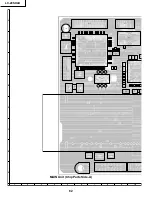
66

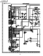
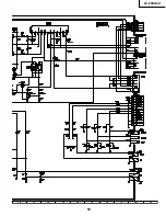
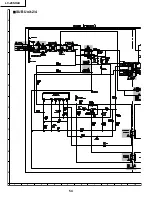
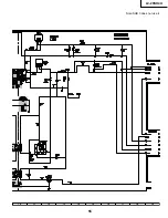
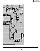
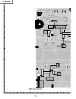
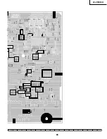
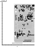
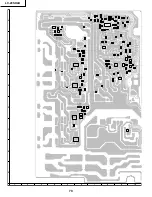
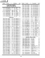
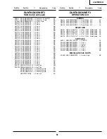
MAIN Unit (Chip Parts Side-B)

C1310

C1311

C1312

C1313

C1314

C1315

C1316

C1317

C1318

C1319

C1320

C1321

C1323

C1324

TL2001

C1325

C1327

R1300

C1328

C1329

R1301

R1302

R1303

TL1067

R1304

TL1068

R1305

TL1069

R1306

R1307

R1308

C1330

C1331

C1332

TL1070

TL1071

TL2012

TL2013

TL1073

TL2014

TL1074

TL2015

TL2016

TL1076

TL2017

TL2018

TL2019

R1316

TL2020

TL2021

TL2022

TL2023

C1348

TL2024

TL2025

TL2026

R1323

TL2027

TL2028

TL2029

R1327

R1329

TL2030

TL2031

TL2032

TL2033

TL2034

R1331

TL2037

TL2038

TL2039

TL2040

TL2041

TL2042

TL2044

TL2045

TL2047

TL2048

TL2049

TL2050

TL1302

C1201

C1205

C1206

C1207

Q1204

Q1205

C1209

Q1206

Q1207

Q1208

Q1209

C1210

C1211

C1212

C1213

Q1210

C1214

Q1211

C1215

Q1212

Q1213

Q1214

C1219

C1220

C1226

D1202

C1227

D1203

FB1300

C1229

D1206

D1207

R1207

R1208

C1231

R1209

C1233

C1234

D1210

C1236

C1237

R1210

R1211

R1212

R1213

R1214

R1216

R1217

R1218

R1219

R1220

R1221

R1222

R1223

R1224

R1227

R1228

L1300

L1301

R1229

L1302

C2001

C2002

R1230

C2004

R1231

Q2001

C2005

R1232

C2006

R1233

Q2003

C2007

R1234

R1235

C2009

R1236

R1237

R1239

C2011

R1240

C2014

R1241

C2015

R1242

C2016

C2017

C2018

R1247

R1248

R1250

R1251

R1252

R2001

R2003

R2006

R2009

IC2004

IC2005

R2010

R2011

R2012

R2013

R2014

R2018

R2019

R2020

R2021

R2022

R2024

R2026

R2027

R2028

R2030

R2033

R2034

R2035

R2036

R2038

R2040

R2041

R2042

R2043

R2044

R2046

R2047

R2048

TL1201

R2055

TL1202

TL1203

R2057

TL1204

R2058

TL1205

TL1206

TL1207

TL1208

TL1209

R2063

TL1210

R2065

TL1211

TL1212

R2066

TL1213

R2067

TL1214

R2071

C1300

C1302

C1303

Q1300

C1304

TL1040

C1305

Q1301

C1306

C1307

TL1044

Q1305

C1309

Содержание LC 13SH4U

Страница 1: ...only The contents are subject to change without notice LCD COLOR TELEVISION CONTENTS IMPORTANT SERVICE SAFETY PRECAUTION 2 SPECIFICATIONS 5 OPERATION MANUAL 6 DIMENSIONS 8 REMOVING OF MAJOR PARTS 9 ADJUSTING PROCEDURE OF EACH SECTION 13 PUBLIC MODE SETTING PROCEDURE 24 TROUBLE SHOOTING TABLE 32 MAJOR IC INFORMATIONS 36 BLOCK DIAGRAM 38 OVERALL WIRING DIAGRAM 40 DESCRIPTION OF SCHEMATIC DIAGRAM 42 ...

Страница 2: ...hich do not have the same safety characteristics as the factory recommended replacement parts shown in this service manual may create shock fire or other hazards WARNING 1 For continued safety no modification of any circuit should be attempted 2 Disconnect AC power before servicing BEFORE RETURNING THE RECEIVER Fire Shock Hazard Before returning the receiver to the user perform the following safet...

Страница 3: ...ées dans ce manuel peut provoquer des électrocutions incendies radiations X ou autres accidents AVERTISSEMENT 1 N entreprendre aucune modification de tout circuit C est dangereux 2 Débrancher le récepteur avant toute réparation VERIFICATIONS CONTRE L INCEN DIE ET LE CHOC ELECTRIQUE Avant de rendre le récepteur à l utilisateur effectuer les vérifications suivantes 1 Inspecter tous les faisceaux de ...

Страница 4: ... is higher than the conventional lead solder by 40 C and as it has poor solder wettability you may be apt to keep the soldering bit in contact with the PWB for extended period of time However Since the land may be peeled off or the maximum heat resistance temperature of parts may be exceeded remove the bit from the PWB as soon as you confirm the steady soldering condition Lead free solder contains...

Страница 5: ...UDIO IN Terminals AUDIO OUT AUDIO OUT Antenna F Type Headphone Mini jack for stereo ø3 5 mm OSD language English Spanish French Power supply AC 120V 60Hz Power consumption 70 W 0 8 W standby AC 120V Weight 15 2 lbs 6 9 kg w o accessories ËAs a part of policy of continuous improvement SHARP reserves the right to make design and specification changes for product improve ment without prior notice The...

Страница 6: ...er part while securely holding down the stand with your other hand How to adjust the angle Speaker Listening with Headphones 20 VOLUME Plug the headphone mini plug into the headphone jack located on the side of the LCD TV set Adjust the sound volume using VOL on the remote control NOTE NOTE Headphones are not included in the supplied accessories No sound is heard from the main unit speakers when a...

Страница 7: ...ctions below Place batteries with their terminals corresponding to the and indications Different types of batteries have different characteristics Do not mix batteries of different types Do not mix old and new batteries Mixing old and new batteries can shorten the life of new batteries and or cause old batteries to leak chemicals Remove batteries as soon as they are depleted Chemicals that leak fr...

Страница 8: ...U 8 DIMENSIONS 315 16 100 3 15 16 100 1557 64 403 3 2427 64 620 1711 64 436 125 32 45 3 35 64 89 8 727 32 199 2 2 1 64 51 2 3 32 53 15 3 64 382 17 1 16 433 including rubber foot 11 27 32 300 8 53 32 129 Unit mm ...

Страница 9: ...ove the cabinet B after opening from the direction of an arrow 5 Detach the connector from each PWB Cabinet A Cabinet B Stand Stand cover 4 2 3 3 1 P6703 P6702 P6701 P6700 SC1001 SC1002 SC1000 SC2003 SC1201 P7301 P3902 SC2002 SC2001 P3901 P3301 SC3601 CN1 CN2 CN3 SC4201 SC4001 P6705 P3601 SC6701 5 5 5 5 5 5 5 5 5 Main PWB R C LED PWB Sub PWB Inverter PWB Operation PWB ...

Страница 10: ...r PWB and take out the inverter PWB 9 Remove the 2 lock screws from the R C LED PWB and take out the R C LED PWB 10 Remove the 2 lock screws from the operation panel top cover and detach the operation panel top cover 11 Remove the 3 lock screws from the operation PWB and detach the operation PWB 12 Remove the 4 lock screws each from the right and left speakers and take out both the speakers 6 8 10...

Страница 11: ...on deflection sheet diffusion sheet and diffusion plate 15 Detach the lamp holders R top L top and R bottom L bottom from the lamp unit 16 Detach the reflection sheet from the back shield 13 14 Reflection deflection Sheet PSHEPA231WJZZ Diffusion Plate PCOVUA048WJZZ Diffusion Sheet PSHEPA233WJZZ Lamp Holder R Top LHLDZA415WJKZ Lamp Unit x5 KLMP A046WJZZ Reflection Sheet PSHEPA226WJZZ Lamp Holder L ...

Страница 12: ...e QCNW D444WJQZ for service 8 Remove the FFC for connection between Sub unit SC3601 and R C LED unit SC4001 and connect the extended cable QCNW D445WJQZ for service 9 Remove only P6701 side of the lead from between Sub unit P3601 and Inverter unit SC6701 and connect the extended cable QCNW D449WJQZ for service 10 Remove the PWB unit fixing screws main unit 2pcs sub unit 2pcs inverter unit 3pcs Ste...

Страница 13: ...ler 3 Key operation in the adjustment process Basic operation Selecting the receiving channels Using the CH ù Ù keys turn up and down an actual receiving channel Snap press The channels are turned up and down one by one Continuous press The next receivable channel is searched Various adjustments The items are adjusted one by one by selecting on the menu screen and using the cursor key and VOL keys...

Страница 14: ... to peak of the wave be minimized 6 2 TAMP adjustment 1 Receive the standard color bar signal 2 See if the Y reading maximum on Adjustment Process Page 2 is within the range in the following table If not adjust the NTSC TAMP setting on the same page to have the Y reading maximum within this range Reference Adjustment Process Menu Page 2 0 1 2 3 4 5 6 7 8 9 10 11 12 13 14 15 16 17 18 19 20 21 22 23...

Страница 15: ...from the center y 0 285 0 004 0 01 Radius from the center White 40 x 0 264 0 002 0 01 Radius from the center y 0 272 0 002 0 01 Radius from the center Adjusting with the bus Gain RGB GAIN Fix the G setting at 0 Vary the R and B settings accordingly Adjustment range 40 Cut off RGB CUTOFF2 Reduce the two strong colors Adjustment range Down to 40 Reading with Minolta CA 210 7 Factory settings 7 1 Mak...

Страница 16: ...E X NONE BLOCK NONE TV GUIDELINES TV Y NONE BLOCK NONE TV Y7 NONE BLOCK NONE TV G NONE BLOCK NONE TV PG NONE BLOCK NONE TV 14 NONE BLOCK NONE TV MA NONE BLOCK NONE BLOCK CONTENT D BLANK BLOCK BLANK UN BLOCK L BLANK BLOCK BLANK UN BLOCK S BLANK BLOCK BLANK UN BLOCK V BLANK BLOCK BLANK UN BLOCK FV BLANK BLOCK BLANK UN BLOCK CAN ENGLISH RATINGS C NONE BLOCK NONE C8 NONE BLOCK NONE G NONE BLOCK NONE P...

Страница 17: ...E THE ADJUSTMENT PROCEDURES R GAIN 0 WHITE BALANCE ADJUSTMENT 2 SEE THE ADJUSTMENT PROCEDURES G GAIN 0 WHITE BALANCE ADJUSTMENT 2 SEE THE ADJUSTMENT PROCEDURES B GAIN 0 WHITE BALANCE ADJUSTMENT 2 SEE THE ADJUSTMENT PROCEDURES RGB GAMMA 1 0 RGB γ COEFFICIENT SETTING NOT USED TABLE OF VARIOUS SETTINGS 9 I2C DATA 0 I2C BUS CONTROL IC DATA WRITE AND READ NOT USED I2C DATA WAIT WRITE AND READ EXECUTED ...

Страница 18: ...NPUT NOT USED OTHER 0775 EQUALIZER SETTING WITH OTHER INPUT THAN TV NOT USED BAND5 CNT TV 0025 EQUALIZER SETTING WITH TV INPUT NOT USED OTHER 0025 EQUALIZER SETTING WITH OTHER INPUT THAN TV NOT USED BAND5 MAX TV 0825 EQUALIZER SETTING WITH TV INPUT NOT USED OTHER 0825 EQUALIZER SETTING WITH OTHER INPUT THAN TV NOT USED Page No Item Initial Function Response precautions on servicing Value Do not ch...

Страница 19: ...SHARP V 100 V PICTURE QUALITY SETTING COMPOSITE S VIDEO NOT USED SECAM AV SHARP H1 150 H PICTURE QUALITY SETTING 1 COMPOSITE S VIDEO NOT USED SECAM AV SHARP H2 150 H PICTURE QUALITY SETTING 2 COMPOSITE S VIDEO NOT USED VIDEO ADJUSTMENT DVP7 PAL60 AV CONT 128 IMAGE SETTING COMPOSITE S VIDEO NOT USED PAL60 AV BRIGHT 128 BRIGHTNESS SETTING COMPOSITE S VIDEO NOT USED PAL60 AV COLOR 37 COLOR DENSITY SE...

Страница 20: ...28 TINT SETTING TV NOT USED 525I SHARP V 100 V PICTURE QUALITY SETTING TV NOT USED 525I SHARP H1 150 H PICTURE QUALITY SETTING 1 TV NOT USED 525I SHARP H2 150 H PICTURE QUALITY SETTING 2 TV NOT USED 525P CONT 133 IMAGE SETTING COMPOSITE S VIDEO NOT USED 525P BRIGHT 128 BRIGHTNESS SETTING COMPOSITE S VIDEO NOT USED 525P COLOR 52 COLOR DENSITY SETTING COMPOSITE S VIDEO NOT USED 525P TINT 128 TINT SE...

Страница 21: ...SED COMPSYNC 3 SYNC JUDGMENT THRESHOLD COLOR DIFFERENCE INPUT NOT USED EDS TEST 10 DURATION UNTIL JUDGMENT OF NO EDS TIME DATA SECONDS NOT USED TUNER SETTINGS TUNER2 AFT FARTIME 50 CHANNEL PRESET TIME ADJUSTMENT 1 NOT USED AFT NEARTIME 30 CHANNEL PRESET TIME ADJUSTMENT 2 NOT USED AFT NEARMTIME 10 CHANNEL PRESET TIME ADJUSTMENT 3 NOT USED AFT 1STEPTIME 10 CHANNEL PRESET TIME ADJUSTMENT 4 NOT USED A...

Страница 22: ... Time of Day Greenwich Mean Time 1 SUN 0 23 0 59 1990 X 1 12 1 31 7 0 23 TIME MIN YEAR MONTH DAY WEEK TIME 10 0 0 0 0 0 0 0 0 0 0 0 0 0 Local Time Zone DST Use Reset SEC L bit Z bit D bit D bit 11 D 0 L 0 Z 0 D 0 12 0 0 0 0 13 Adjustment process auto clock display In the adjustment process the local time can be freely obtained Each time the local time is known the colors of the following items cha...

Страница 23: ...rned off and the usual display appears instead when the power is turned on again 2 Test pattern displayed The following test pattern appears onscreen The DVP test pattern comes in 22 different types 1 Black white Size Minimum 2 Black white Size Small 3 Black white Size Medium 4 Black white Size Large 5 Crosshatch Spacing Minimum 6 Crosshatch Spacing Small 7 Crosshatch Spacing Medium 8 Crosshatch S...

Страница 24: ...e password input screen displayed Procedure The input starts with the leftmost digit Use the numeric keys 1 thru 9 and 10 0 keys on the remote con troller The other keys are not acceptable With a numeric key input will change to The input position will move one digit to the right With all the 3 digits entered the password will be verified 3 The 3 digit password is now verified The password 0 2 7 p...

Страница 25: ...tings get initialized The adjustment process remains intact 4 Public Mode Menu The guidance is not displayed onscreen Setup procedure To move the cursor up and down use the cursor UP DOWN key remote controller and CH ù Ù key remote controller and set To change the settings use the cursor RIGHT LEFT key remote controller and VOL key remote controller and set To save new settings keep the cursor at ...

Страница 26: ...tive of pre adjusted value When the sound volume is set higher than the MAX setting by the adjusting process or headphone the sound volume control operation is prohibited for turn up and the sound volume should be turned down to MAX in this state Selection Default Explanation Limit in Setting Exception Remarks Selection between Variable and Fixed loop provided Variable Sound volume is fixed and ma...

Страница 27: ... also in the initial EZ Setup after power ON irrespective of setting Selection Default Explanation Limit in Setting Exception Remarks Selection between Respond and No respond loop provide Respond All the operations by keys except the power key of the unit can be invalidated Inspection mode and hotel menu mode can be started irrespective of setting All the keys can be used in adjustment process ins...

Страница 28: ...g the setting of SOUND ONLY MODE is changed to OFF and selecting operation is made prohibited When CC has already been ON CLOSED CAPTION is displayed Selection Default Explanation About options Limit in Setting Exception Remarks Selection between Normal TV CH COMPONENT AV1 and AV2 loop provide Normal In power ON the input source to be started or channel can be set In standard mode the operation fo...

Страница 29: ...ke up timer channel items are not displayed or the operation is prohibited Basically they are not displayed The following keys are invalidated CH direct tuning button FLASHBACK input However the keys input switching and CH keys of the unit for menu operation remain valid None In the following case setting is cancelled and mode is changed to Variable 1When the setting of Input mode start is set to ...

Страница 30: ...3 The key functions in the sound only mode setup process and sound only mode process are referred to in Table of Key Allocation in Sound Only Mode and Table of Key Functions in Sound Only Mode 4 To turn off the power with the power key off timer or no signal power supply in the sound only mode first end the sound only mode then call the BACKLIGHT mode and finally turn off the power 5 Let s suppose...

Страница 31: ...rror detect on seconds Description of pressed key displayed for 3 Sound only mode setup message displayed seconds Current BACKLIGHT mode status displayed Sound only mode setup message displayed Current BACKLIGHT mode status displayed Table of Key Allocation in Sound Only Mode Unit keys Remote control keys Unit keys Remote control Key POWER INPUT MENU CH VOL POWER PIC FLIP DISPLAY SLEEP MENU CURSOR...

Страница 32: ...V input at F6700 thru F6704 Check the primary side of T7001 IC7301 and its peripheral circuits Disconnect F6700 thru F6704 Is the load short circuited Check the related line IC1004 and its peripheral circuits Is pin 187 of IC1004 at H or pulse Check the inverter unit and fluorescent lamp and replace as required Check the primary side of T7001 Q3305 and its peripheral circuits Check the connections...

Страница 33: ...nput at pin 24 of S terminal detector IC2003 as specified No Is the input at pin 40 of IC1004 as specified Are the voltages at pins 6 7 and 9 of tuner as specified No image at all Check the microprocessor s adjustment process menu for wrong settings No TV output No Video 1 output No S Video output No Component output Check the LCD panel voltage and waveform Yes Yes Check the related line Yes Check...

Страница 34: ... of IC1300 About 8V Pins 65 and 66 of IC1300 About 5V Pins 11 12 and 13 of IC1300 About 3 3V Check the line from power circuit to pin 7 of IC3301 No sound from monitor output Check IC1300 and its peripheral circuits Check the line from pin 58 of IC2003 to Q3901 Q3902 and Q3903 Are there audio signal outputs from pins 36 Rch and 37 Lch of IC1300 Is the collector signal of Q3901 at L Check the lines...

Страница 35: ...and its peripheral circuits Is the input at pin 31 of IC1004 as specified Check pin 15 of SC2002 No Are the inputs at pins 21 and 33 of IC1004 as specified Check the CB and CR lines of SC2001 and their peripheral circuits Check the microprocessor s adjustment process menu for wrong settings No color on Video No color on S Video No color on Component ...

Страница 36: ... bus 2 system 28 P72 I O SCL2 Serial clock line 2 for I2C bus 2 system EEPROM 29 P71 I O SCL1 Serial clock line 1 for I2C bus 2 system others 30 SDA1 I O SCA1 Serial data line 1 for I2C bus 2 system 31 P67 O TxD TxD at flash write 32 P66 O RxD RxD at flash write 33 P65 O SCLK Clock input at flash write 34 P64 O BUSY Busy output at flash write 35 TxD0 O MPWEL Data signal input for DVP 4 line serial...

Страница 37: ...light up 70 P22 O INV_POW Separately excited inverter power control 71 P21 O VGH Panel power control 72 P20 O POWout DC DC control output 73 P17 I ADPPOW Adaptor ON OFF input 74 P16 O DACOUTCON Gradation control IC output control 75 P15 O N C 76 P14 O N C 77 P13 O N C 78 P12 O MP_DA Gradation control IC data output 79 P11 O MP_CLK Temperature sensor or gradation control IC clock output 80 P10 O DD...

Страница 38: ...2C 3 3V 5V 3V IMZ1A 2 To MAIN MICON AFT AV IN S SW SP 2 1 0 1 0W LA4635A ANALOG SP_MUTE SLEEP S_STBY HP Front Jack 3 5 STEREO SP 18 432MHz SOUND_PROCESSOR RH IXB302WJN1Q ANA_IN 1 SC1_IN SC2_IN SC4_IN SC3_IN DACM_OUT SC1_OUT SC2_OUT DACA_OUT SCL SDA I2C 3 3V AV OUT AUDIO OUT ANA_IN2 AUDIO_POWER_AMP SIF AMP AUDIO IN VIDEO IN SC IN SY IN ...

Страница 39: ...in Cb in 33pin RED GREEN BLUE CK SP T CON QS Cr in 21 pin D Y in 40pin C in 31pin MAIN_PWB INV_PWB LCD_Panel LAMP GRADATION SEQUENCE LINE REVERSING LCD PANEL VGA 50 20 30FFC POWER VSH 3 3V VLS 5 0V VGH 23 0V VGL 7 0 V E2PROM VHIBR24L64F 1Y S DETECT CVBS in 13pin SHORT DETECT OFL LERRER MPCLK MPRDA MPRCS H OUT V OUT LAMP error FOUR WIRE SYSTEM SERIAL 3 3V BD8120FP KEY RMC4001 R C CSYNC VSYNC MPWEH ...

Страница 40: ...LC 20SH4U 8 7 10 9 6 5 4 3 2 1 A B C D E F G H 40 OVERALL WIRING DIAGRAM ...

Страница 41: ...LC 20SH4U 41 17 16 19 18 15 14 13 12 11 10 ...

Страница 42: ... 3 DOES NOT USE IT CAUTION This circuit diagram is original one therefore there may be a slight difference from yours SAFETY NOTES 1 DISCONNECT THE AC PLUG FROM THE AC OUTLET BEFORE REPLACING PARTS 2 SEMICONDUCTOR HEAT SINKS SHOULD BE REGARDEDAS POTENTIAL SHOCK HAZARDS WHEN THE CHASSIS IS OPERATING IMPORTANT SAFETY NOTICE PARTS MARKED WITH å ARE IMPORTANT FOR MAINTAINING THE SAFETY OF THE SET BE S...

Страница 43: ...LC 20SH4U 43 6 5 4 3 2 1 A B C D E F G H SCHEMATIC DIAGRAM Ë INVERTER Unit ...

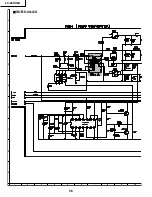
Страница 44: ...LC 20SH4U 8 7 10 9 6 5 4 3 2 1 A B C D E F G H 44 ËMAIN Unit 1 4 ...

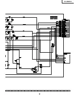
Страница 45: ...LC 20SH4U 45 17 16 19 18 15 14 13 12 11 10 ...

Страница 46: ...LC 20SH4U 8 7 10 9 6 5 4 3 2 1 A B C D E F G H 46 ËMAIN Unit 2 4 ...

Страница 47: ...LC 20SH4U 47 17 16 19 18 15 14 13 12 11 10 ...

Страница 48: ...LC 20SH4U 8 7 10 9 6 5 4 3 2 1 A B C D E F G H 48 ËMAIN Unit 3 4 ...

Страница 49: ...LC 20SH4U 49 17 16 19 18 15 14 13 12 11 10 ...

Страница 50: ...LC 20SH4U 8 7 10 9 6 5 4 3 2 1 A B C D E F G H 50 ËMAIN Unit 4 4 ...

Страница 51: ...LC 20SH4U 51 17 16 19 18 15 14 13 12 11 10 ...

Страница 52: ...LC 20SH4U 8 7 10 9 6 5 4 3 2 1 A B C D E F G H 52 ËSUB Unit 1 4 ...

Страница 53: ...LC 20SH4U 53 17 16 19 18 15 14 13 12 11 10 ...

Страница 54: ...LC 20SH4U 8 7 10 9 6 5 4 3 2 1 A B C D E F G H 54 ËSUB Unit 2 4 ...

Страница 55: ...LC 20SH4U 55 17 16 19 18 15 14 13 12 11 10 Note SUB 3 does not use it ...

Страница 56: ...LC 20SH4U 8 7 10 9 6 5 4 3 2 1 A B C D E F G H 56 ËSUB Unit 4 4 ...

Страница 57: ...LC 20SH4U 57 17 16 19 18 15 14 13 12 11 10 ...

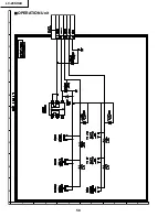
Страница 58: ...LC 20SH4U 58 6 5 4 3 2 1 A B C D E F G H ËOPERATION Unit ...

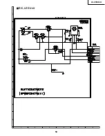
Страница 59: ...LC 20SH4U 59 6 5 4 3 2 1 A B C D E F G H Ë R C LED Unit ...

Страница 60: ... SC1001 1 20 SC1002 L1000 C1339 a C1340 C1341 L1202 LUG2001 1 2 14 15 SC2001 1 2 C1009 C1204 Q1201 Q1202 C1208 C1015 D1201 1 54 55 108 109 162 163 216 IC1004 R1202 1 1 4 15 28 IC1201 1 2 19 20 P2001 R1215 C1054 C1064 R1046 R1048 C1090 30 31 50 51 R2045 R2049 R2050 R2051 R2052 R2053 R2054 R2056 R2059 R2060 R2061 R2062 X1000 ...

Страница 61: ...Q1202 C1208 X1300 C1216 C1217 C1218 1 4 5 8 Q1215 Q1216 C1221 C1222 C1223 C1224 D1204 D1205 D1208 D1209 C1230 1 4 15 IC1201 1 2 3 IC1202 1 7 8 14 IC1203 1 3 4 5 IC1204 C1235 R1225 R1226 L1303 C2003 Q2002 C2012 C2013 R1245 R1253 R2005 R2007 R2008 1 3 4 5 IC2001 1 30 1 50 51 80 81 100 R2015 R2016 R2017 R2023 R2025 R2031 R2045 R2059 R2062 FL2001 C1301 C1308 KD034WE QPWBXD034WJN1 1 5 1 W ...

Страница 62: ... C1034 IC1004 C1035 R1201 R1202 C1036 C1037 C1038 R1204 C1039 R1205 IC1201 C1040 C1041 P2001 C1042 C1043 C1044 C1045 C1046 C1047 R1215 C1049 C1050 C1052 C1053 C1054 C1055 C1056 C1057 C1058 C1059 C1060 C1061 C1062 C1063 C1064 C1065 C1066 C1067 C1068 C1069 R1046 R1048 C1070 C1071 R1049 C1072 C1073 C1074 C1075 C1076 C1077 R1050 C1078 C1079 R1051 C1080 C1081 C1082 C1083 C1084 C1090 R2037 R2039 R2045 R...

Страница 63: ... Q1216 C1221 C1222 C1223 C1224 C1225 C1228 D1204 D1205 R1201 2 R1203 D1208 R1204 D1209 R1205 C1230 IC1201 IC1202 C1232 IC1203 IC1204 D1211 C1235 C1238 R1225 R1226 C2003 Q2002 R1238 C2010 C2012 C2013 R1243 R1244 R1245 R1246 R1249 R1253 R2002 R2004 R2005 R2007 R2008 IC2001 IC2003 R2015 R2016 R2017 R2023 R2025 R2029 R2031 R2032 R2037 R2039 R2045 R2059 R2062 R2064 R2068 FL2001 C1301 C1308 ...

Страница 64: ...9 C1220 C1226 D1202 C1227 FB1300 C1229 D1206 R1207 R1208 C1231 R12 C1234 C1236 C1237 R12 R121 R1214 R1216 R1218 R1219 R1221 R1223 R1224 R1227 R1228 L1300 L1301 R1229 L1302 L1303 C2001 C2002 R1230 C2004 Q2001 C2005 R1232 C2006 R1233 C2007 R1234 R1235 C2009 R1237 R1239 C2011 R1240 C2014 R1241 R1242 C2016 C2017 R1247 R1250 R1251 R1252 R2001 R2003 R2009 1 3 4 5 IC2004 IC2005 R2010 R2011 R2018 R2019 R2...

Страница 65: ...1016 C1017 C1018 C1019 C1211 C1212 C1213 C1215 C1021 C1022 C1023 D1000 C1025 R1002 R1005 IC1000 R1008 IC1001 4 5 8 IC1002 1 5 IC1003 D1203 R1010 R1011 R1206 R1013 R1014 209 R1018 D1210 210 13 C1048 R1021 R1022 R1025 R1028 C1051 R1223 R1030 R1038 R1039 Q2003 R1040 R1041 R1042 R1043 R1044 R1047 C2015 R1053 R1054 R1055 R1057 R1058 R1059 C1085 C1086 C1087 R1060 C1088 R1061 R1062 R1063 R1064 R1065 R106...

Страница 66: ...Q1210 C1214 Q1211 C1215 Q1212 Q1213 Q1214 C1219 C1220 C1226 D1202 C1227 D1203 FB1300 C1229 D1206 D1207 R1207 R1208 C1231 R1209 C1233 C1234 D1210 C1236 C1237 R1210 R1211 R1212 R1213 R1214 R1216 R1217 R1218 R1219 R1220 R1221 R1222 R1223 R1224 R1227 R1228 L1300 L1301 R1229 L1302 C2001 C2002 R1230 C2004 R1231 Q2001 C2005 R1232 C2006 R1233 Q2003 C2007 R1234 R1235 C2009 R1236 R1237 R1239 C2011 R1240 C20...

Страница 67: ...000 C1025 R1001 R1002 R1003 R1004 R1005 R1006 R1007 IC1000 R1008 R1009 IC1001 IC1002 IC1003 D1203 R1010 R1011 R1012 R1206 R1013 R1014 R1015 R1016 R1017 R1018 D1210 R1019 C1048 R1020 R1021 R1022 R1023 R1024 R1025 R1026 R1027 R1028 R1029 C1051 R1030 R1031 R1032 R1033 R1034 R1035 R1036 R1037 R1038 R1039 Q2003 R1040 R1041 R1042 R1043 R1044 R1045 R1047 R1052 R1053 R1054 R1055 R1056 R1057 R1058 R1059 C1...

Страница 68: ...LC 20SH4U 8 7 10 9 6 5 4 3 2 1 A B C D E F G H 68 ...

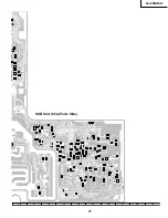
Страница 69: ...LC 20SH4U 69 17 16 19 18 15 14 13 12 11 10 SUB Unit Wiring Side ...

Страница 70: ...LC 20SH4U 8 7 10 9 6 5 4 3 2 1 A B C D E F G H 70 ...

Страница 71: ...LC 20SH4U 71 17 16 19 18 15 14 13 12 11 10 SUB Unit Chip Parts Side ...

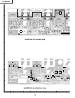
Страница 72: ...LC 20SH4U 8 7 10 9 6 5 4 3 2 1 A B C D E F G H 72 INVERTER Unit Wiring Side INVERTER Unit Chip Parts Side ...

Страница 73: ...LC 20SH4U 73 17 16 19 18 15 14 13 12 11 10 ...

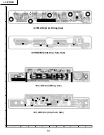
Страница 74: ...LC 20SH4U 74 6 5 4 3 2 1 A B C D E F G H OPERATION Unit Wiring Side OPERATION Unit Chip Parts Side R C LED Unit Wiring Side R C LED Unit Chip Parts Side ...

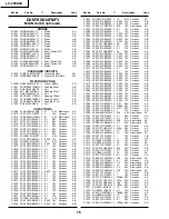
Страница 75: ...nts suivants 1 NUMERO DU MODELE 2 NO DE REF 3 NO DE PIECE 4 DESCRIPTION in CANADA Contact SHARP Electronics of Canada Limited Phone 416 890 2100 Ref No Part No Description Code Ref No Part No Description Code PRINTED WIRING BOARD ASSEMBLYS NOT REPLACEMENT ITEM DUNTKD034FMF3 MAIN Unit DUNTKD035WEF3 SUB Unit DUNTKD036WEF3 OPERATION Unit DUNTKD037WEF3 R C LED Unit DUNTKD057FMF3 INVERTER Unit DUNTKD03...

Страница 76: ...055 VCKYCZ1AB104KY J 0 1 10V Ceramic AB C1056 VCKYCZ1AB104KY J 0 1 10V Ceramic AB C1057 VCKYCZ1AB333KY J 0 033 10V Ceramic AB C1058 VCKYCZ1AB333KY J 0 033 10V Ceramic AB C1059 VCKYCZ1AB333KY J 0 033 10V Ceramic AB C1060 VCKYCZ1AB333KY J 0 033 10V Ceramic AB C1061 VCCCCY1HH5R0CY J 5p 50V Ceramic AA C1062 VCKYCZ1AB104KY J 0 1 10V Ceramic AB C1063 VCKYCZ1AB104KY J 0 1 10V Ceramic AB C1064 VCCCCY1HH5R...

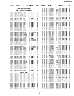
Страница 77: ...VRS CY1JF103JY J 10k 1 16W Metal Oxide AA R1046 VRS CJ1JF100JY J 10 1 16W Metal Oxide AA R1047 VRS CH1JF103JY J 10k 1 16W Metal Oxide AA R1049 VRS CY1JF105JY J 1M 1 16W Metal Oxide AA R1050 VRS CY1JF560JY J 56 1 16W Metal Oxide AA R1051 VRS CY1JF000JY J 0 1 16W Metal Oxide AA R1052 VRS CY1JF470JY J 47 1 16W Metal Oxide AA R1053 VRS CY1JF103JY J 10k 1 16W Metal Oxide AA R1054 VRS CY1JF470JY J 47 1 ...

Страница 78: ...al Oxide AA R2013 VRS CY1JF103JY J 10k 1 16W Metal Oxide AA R2015 VRS CY1JF103JY J 10k 1 16W Metal Oxide AA R2016 VRS CY1JF103JY J 10k 1 16W Metal Oxide AA R2017 VRS CJ1JF223JY J 22k 1 16W Metal Oxide AA R2018 VRS CY1JF101JY J 100 1 16W Metal Oxide AA R2021 VRS CY1JF153JY J 15k 1 16W Metal Oxide AA R2022 VRS CY1JF223JY J 22k 1 16W Metal Oxide AA R2023 VRS CY1JF101JY J 100 1 16W Metal Oxide AA R202...

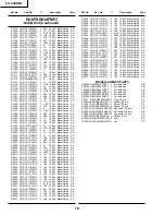
Страница 79: ...VCESKA1HM225M J 2 2 50V Electrolytic AB C3302 VCESKA1HM225M J 2 2 50V Electrolytic AB C3303 VCKYCY1HB153KY J 0 015 50V Ceramic AA C3304 VCKYCY1HB153KY J 0 015 50V Ceramic AA C3306 VCESKA1HM105M J 1 50V Electrolytic AB C3307 VCESKA1HM105M J 1 50V Electrolytic AB C3308 VCKYCY1HB102KY J 1000p 50V Ceramic AA C3309 VCKYCY1HB102KY J 1000p 50V Ceramic AA C3310 VCESKA1CM107M J 100 16V Electrolytic AC C331...

Страница 80: ... AA R7004 VRS CY1JF000JY J 0 1 16W Metal Oxide AA R7005 VRS CY1JF1R0JY J 1 1 16W Metal Oxide AA R7006 VRS CY1JF000JY J 0 1 16W Metal Oxide AA R7007 VRS TQ2BD683JY J 68k 1 8W Metal Oxide AA R7009 VRS CY1JF223JY J 22k 1 16W Metal Oxide AA R7010 VRS CY1JF103JY J 10k 1 16W Metal Oxide AA R7301 VRS CY1JF104DY J 100k 1 16W Metal Oxide AA R7302 VRS CY1JF104DY J 100k 1 16W Metal Oxide AA R7303 VRS CY1JF33...

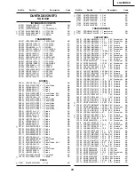
Страница 81: ...PEZZ J Screw AB HM7731 LX GZ3002PEZZ J Screw AB HM7732 LX GZ3002PEZZ J Screw AB HM7733 LX GZ3002PEZZ J Screw AB HM7734 LX GZ3002PEZZ J Screw AB HM7735 LX GZ3002PEZZ J Screw AB RDA7701PRDARA178WJFW J Heat Sink AM RDA7702PRDARA185WJFW J Heat Sink AL QCNW D459WJQZ J Connecting Cord AC QCNW D513WJPZ J Connecting Cord AC QCNW D692WJQZ J Connecting Cord AD XBPS730P10JS0 J Screw x4 AA DIODES D4201 RH EX0...

Страница 82: ...ODES D6700 VHDDAN202K 1Y J Diode AB D6701 VHDDAN202K 1Y J Diode AB D6702 VHDMA157A 1Y J Diode AC D6703 VHDMA157A 1Y J Diode AC D6704 VHDDAN202K 1Y J Diode AB D6705 VHDDAN202K 1Y J Diode AB D6707 VHDMA157A 1Y J Diode AC D6708 VHDMA157A 1Y J Diode AC D6709 VHDDAN202K 1Y J Diode AB D6710 VHDMA157A 1Y J Diode AC D6711 VHDDAN202K 1Y J Diode AB COILS L6700 RCiLPA373WJZZ J Coil AC L6701 RCiLPA373WJZZ J C...

Страница 83: ...AA R6727 VRD RA2BE562JY J 5 6k 1 8W Carbon AA R6728 VRD RA2EE182JY J 1 8k 1 4W Carbon AA R6729 VRS TW2ED182JY J 1 8k 1 4W Metal Oxide AA R6730 VRS CY1JF562JY J 5 6k 1 16W Metal Oxide AA R6731 VRS CY1JF333JY J 33k 1 16W Metal Oxide AA R6732 VRS CY1JF471JY J 470 1 16W Metal Oxide AA R6733 VRS CY1JF824JY J 820k 1 16W Metal Oxide AA R6734 VRS CY1JF562JY J 5 6k 1 16W Metal Oxide AA R6743 VRS CY1JF563JY...

Страница 84: ... 5 XEBSN30P08000 J Screw x1 AA 5 Not Available 20 LCD Panel Unit Ass y 5 1 RLCDTA025WJZZ J 20 LCD Panel Unit DB 5 2 Not Available Back Shield Ass y 5 2 1 PSLDMA738WJFW J Back Shield AX 5 2 2 LHLDZA412WJKZ J Lamp Holder Bottom L AG 5 2 3 LHLDZA413WJKZ J Lamp Holder Bottom R AF 5 2 4 PMLT A150WJZZ J Spacer x2 AD 5 2 5 PSHEPA226WJZZ J Reflection Sheet AN 5 2 6 TCAUZA031WJZZ J Caution Label AB å 5 3 K...

Страница 85: ...20 4 1 1 1 4 2 4 3 4 4 1 2 1 4 1 4 1 3 1 3 1 1 2 R C LED PWB Main PWB Sub PWB Inverter PWB Operation PWB 5 2 6 5 2 1 5 2 4 5 2 4 5 2 5 2 2 5 2 3 5 2 5 11 9 12 5 4 5 5 5 3 5 6 5 8 5 7 5 1 5 11 5 10 5 10 13 22 22 22 6 14 2 7 18 8 17 21 2 3 2 2 2 4 2 1 2 5 15 16 19 3 3 2 3 6 3 3 3 1 3 5 3 4 1 1 4 1 1 3 1 1 3 1 1 1 1 1 4 23 1 1 5 1 1 6 A A C C I C C 5 9 ...

Страница 86: ...Bag S5 TLABKA025WJZZ No Label SERVICE JIGS USE FOR SERVICING QCNW A555WJZZ J Extension Cable 20 pin AU SC1002 LCD QCNW A556WJZZ J Extension Cable 50 pin AU SC1000 LCD QCNW B784WJZZ J Extension Cable 30 pin BA SC1001 LCD QCNW C461WJQZ J Extension Cable 15 pin x2 CD SC1201 P7301 SC2001 P3901 QCNW D402WJQZ J Extension Cable 23 pin CE SC1201 P3902 QCNW D444WJQZ J Extension Cable 5 pin AQ SC2003 SC4201...

Страница 87: ...87 LC 20SH4U PACKING OF THE SET X2 X3 X4 X1 S2 S3 S3 S4 S3 S3 S5 S1 X5 ...

Страница 88: ...ansmitted in any form or by any means electronic mechanical photocopying recording or otherwise without prior written permission of the publisher SHARP CORPORATION AV Systems Group Quality Reliability Control Center Yaita Tochigi 329 2193 Japan TQ1874 S Mar 2005 Printed in Japan MI KG Design and Production Information Design Japan Production NSEC ...

Отзывы: