LC-20SH4U
32
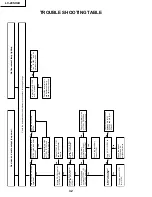
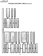
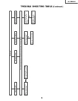
TROUBLE SHOOTING TABLE
Check the secondary
load of T7001.
Is pin (10) of IC1203 at
"H"?
Check the load of
IC1203 and its
peripheral circuits.
Is the primary
oscillation wave of
T7001 as specified?
Are the secondary
outputs of T7001 +5V, -
12V, +35V and +9V?
Is there DC 12V input at
T7701 and pin (8) of
IC7301?
Is the output voltage of
IC1203 as specified?
Check the load of IC701
thru IC703.
Check T7701, IC7701
and their peripheral
circuits.
Check T7701, IC7701
and their peripheral
circuits.
Is there DC 18V input at
F6700 thru F6704?
Check the primary side
of T7001, IC7301 and
its peripheral circuits.
Disconnect F6700 thru
F6704. Is the load short-
circuited?
Check the related
line, IC1004 and its
peripheral circuits.
Is pin (187) of IC1004
at "H" or pulse?
Check the inverter unit
and fluorescent lamp,
and replace as required.
Check the primary side
of T7001, Q3305 and
its peripheral circuits.
Check the connections
between pin (4) of
SC2003 and pin (2) of
SC4201.
No video and audio output (no po
wer)
No fluorescent lamp light-up
No
No
No
No
No
No
No
No
No
Are F6700 thr
u F6704 as
specified?
Replace F6700 thru
F6704.
Yes
Yes
Yes
Yes
Yes
Yes
Yes
Yes
Yes
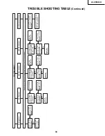
Chec
k the microprocessor's adjustment process men
u f
or wrong settings
.
Содержание LC 13SH4U
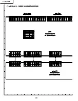
Страница 40: ...LC 20SH4U 8 7 10 9 6 5 4 3 2 1 A B C D E F G H 40 OVERALL WIRING DIAGRAM ...
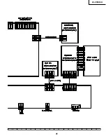
Страница 41: ...LC 20SH4U 41 17 16 19 18 15 14 13 12 11 10 ...
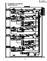
Страница 43: ...LC 20SH4U 43 6 5 4 3 2 1 A B C D E F G H SCHEMATIC DIAGRAM Ë INVERTER Unit ...
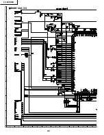
Страница 44: ...LC 20SH4U 8 7 10 9 6 5 4 3 2 1 A B C D E F G H 44 ËMAIN Unit 1 4 ...
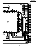
Страница 45: ...LC 20SH4U 45 17 16 19 18 15 14 13 12 11 10 ...
Страница 46: ...LC 20SH4U 8 7 10 9 6 5 4 3 2 1 A B C D E F G H 46 ËMAIN Unit 2 4 ...
Страница 47: ...LC 20SH4U 47 17 16 19 18 15 14 13 12 11 10 ...
Страница 48: ...LC 20SH4U 8 7 10 9 6 5 4 3 2 1 A B C D E F G H 48 ËMAIN Unit 3 4 ...
Страница 49: ...LC 20SH4U 49 17 16 19 18 15 14 13 12 11 10 ...
Страница 50: ...LC 20SH4U 8 7 10 9 6 5 4 3 2 1 A B C D E F G H 50 ËMAIN Unit 4 4 ...
Страница 51: ...LC 20SH4U 51 17 16 19 18 15 14 13 12 11 10 ...
Страница 52: ...LC 20SH4U 8 7 10 9 6 5 4 3 2 1 A B C D E F G H 52 ËSUB Unit 1 4 ...
Страница 53: ...LC 20SH4U 53 17 16 19 18 15 14 13 12 11 10 ...
Страница 54: ...LC 20SH4U 8 7 10 9 6 5 4 3 2 1 A B C D E F G H 54 ËSUB Unit 2 4 ...
Страница 55: ...LC 20SH4U 55 17 16 19 18 15 14 13 12 11 10 Note SUB 3 does not use it ...
Страница 56: ...LC 20SH4U 8 7 10 9 6 5 4 3 2 1 A B C D E F G H 56 ËSUB Unit 4 4 ...
Страница 57: ...LC 20SH4U 57 17 16 19 18 15 14 13 12 11 10 ...
Страница 58: ...LC 20SH4U 58 6 5 4 3 2 1 A B C D E F G H ËOPERATION Unit ...
Страница 59: ...LC 20SH4U 59 6 5 4 3 2 1 A B C D E F G H Ë R C LED Unit ...
Страница 68: ...LC 20SH4U 8 7 10 9 6 5 4 3 2 1 A B C D E F G H 68 ...
Страница 69: ...LC 20SH4U 69 17 16 19 18 15 14 13 12 11 10 SUB Unit Wiring Side ...
Страница 70: ...LC 20SH4U 8 7 10 9 6 5 4 3 2 1 A B C D E F G H 70 ...
Страница 71: ...LC 20SH4U 71 17 16 19 18 15 14 13 12 11 10 SUB Unit Chip Parts Side ...
Страница 72: ...LC 20SH4U 8 7 10 9 6 5 4 3 2 1 A B C D E F G H 72 INVERTER Unit Wiring Side INVERTER Unit Chip Parts Side ...
Страница 73: ...LC 20SH4U 73 17 16 19 18 15 14 13 12 11 10 ...
Страница 87: ...87 LC 20SH4U PACKING OF THE SET X2 X3 X4 X1 S2 S3 S3 S4 S3 S3 S5 S1 X5 ...

