LC-20SH4U
12
»
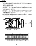
Precautions at the time of the side B(back) service of main, sub and Inverter unit.
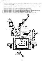
1. Remove the FFC for connection between Main unit (SC1001) and LCD panel (CN1), and connect the extended
cable (QCNW-B784WJZZ) for service.
2. Remove the FFC for connection between Main unit (SC1000) and LCD panel (CN2), and connect the extended
cable (QCNW-A556WJZZ) for service.
3. Remove the FFC for connection between Main unit (SC1002) and LCD panel (CN3), and connect the extended
cable (QCNW-A555WJZZ) for service.
4. Remove only SC1201 side of the lead from between Main unit (SC1201) and Sub unit (P7301), and connect the
extended cable (QCNW-C461WJQZ) for service.
5. Remove only SC2001 side of the lead from between Main unit (SC2001) and Sub unit (P3901), and connect the
extended cable (QCNW-C461WJQZ) for service.
6. Remove only SC2002 side of the lead from between Main unit (SC2002) and Sub unit (P3902), and connect the
extended cable (QCNW-D402WJQZ) for service.
7. Remove the FFC for connection between Main unit (SC2003) and Operation unit (SC4201), and connect the
extended cable (QCNW-D444WJQZ) for service.
8. Remove the FFC for connection between Sub unit (SC3601) and R/C, LED unit (SC4001), and connect the
extended cable (QCNW-D445WJQZ) for service.
9. Remove only P6701 side of the lead from between Sub unit (P3601) and Inverter unit (SC6701), and connect the
extended cable (QCNW-D449WJQZ) for service.
10. Remove the PWB unit fixing screws (main unit : 2pcs, sub unit : 2pcs., inverter unit : 3pcs.)
Step
Part No.
Description
1
QCNW-B784WJZZ
Extension Cable 30-pin Main (SC1001)-LCD panel (CN1)
2
QCNW-A556WJZZ
Extension Cable 50-pin Main (SC1000)-LCD panel (CN2)
3
QCNW-A555WJZZ
Extension Cable 20-pin Main (SC1002)-LCD panel (CN3)
4
QCNW-C461WJQZ
Extension Cable 15-pin Main (SC1201)-Sub (P7301)
5
QCNW-C461WJQZ
Extension Cable 15-pin Main (SC2001)-Sub (P3901)
6
QCNW-D402WJQZ
Extension Cable 23-pin Main (SC2002)-Sub (P3902)
7
QCNW-D444WJQZ
Extension Cable 5-pin Operation (SC4201)-Main (SC2003)
8
QCNW-D445WJQZ
Extension Cable 8-pin R/C, LED (SC4001)-Sub (SC3601)
9
QCNW-D449WJQZ
Extension Cable 13-pin Inverter (SC6701)-Sub (P3601)
SC1001
SC2001
P3901
SC2002
SC1002
SC1201
SC1000
SC2003
SC6701
P3601
P7301
P3902
SC3601
CN1
CN2 CN3
SC4201
SC4001
2
4
3
1
7
9
8
6
5
10
Main PWB
Operation PWB
Inverter PWB
Inverter
PWB
(Side B)
Main PWB
(Side B)
Sub PWB
(Side B)
Sub PWB
R/C, LED PWB
Содержание LC 13SH4U
Страница 40: ...LC 20SH4U 8 7 10 9 6 5 4 3 2 1 A B C D E F G H 40 OVERALL WIRING DIAGRAM ...
Страница 41: ...LC 20SH4U 41 17 16 19 18 15 14 13 12 11 10 ...
Страница 43: ...LC 20SH4U 43 6 5 4 3 2 1 A B C D E F G H SCHEMATIC DIAGRAM Ë INVERTER Unit ...
Страница 44: ...LC 20SH4U 8 7 10 9 6 5 4 3 2 1 A B C D E F G H 44 ËMAIN Unit 1 4 ...
Страница 45: ...LC 20SH4U 45 17 16 19 18 15 14 13 12 11 10 ...
Страница 46: ...LC 20SH4U 8 7 10 9 6 5 4 3 2 1 A B C D E F G H 46 ËMAIN Unit 2 4 ...
Страница 47: ...LC 20SH4U 47 17 16 19 18 15 14 13 12 11 10 ...
Страница 48: ...LC 20SH4U 8 7 10 9 6 5 4 3 2 1 A B C D E F G H 48 ËMAIN Unit 3 4 ...
Страница 49: ...LC 20SH4U 49 17 16 19 18 15 14 13 12 11 10 ...
Страница 50: ...LC 20SH4U 8 7 10 9 6 5 4 3 2 1 A B C D E F G H 50 ËMAIN Unit 4 4 ...
Страница 51: ...LC 20SH4U 51 17 16 19 18 15 14 13 12 11 10 ...
Страница 52: ...LC 20SH4U 8 7 10 9 6 5 4 3 2 1 A B C D E F G H 52 ËSUB Unit 1 4 ...
Страница 53: ...LC 20SH4U 53 17 16 19 18 15 14 13 12 11 10 ...
Страница 54: ...LC 20SH4U 8 7 10 9 6 5 4 3 2 1 A B C D E F G H 54 ËSUB Unit 2 4 ...
Страница 55: ...LC 20SH4U 55 17 16 19 18 15 14 13 12 11 10 Note SUB 3 does not use it ...
Страница 56: ...LC 20SH4U 8 7 10 9 6 5 4 3 2 1 A B C D E F G H 56 ËSUB Unit 4 4 ...
Страница 57: ...LC 20SH4U 57 17 16 19 18 15 14 13 12 11 10 ...
Страница 58: ...LC 20SH4U 58 6 5 4 3 2 1 A B C D E F G H ËOPERATION Unit ...
Страница 59: ...LC 20SH4U 59 6 5 4 3 2 1 A B C D E F G H Ë R C LED Unit ...
Страница 68: ...LC 20SH4U 8 7 10 9 6 5 4 3 2 1 A B C D E F G H 68 ...
Страница 69: ...LC 20SH4U 69 17 16 19 18 15 14 13 12 11 10 SUB Unit Wiring Side ...
Страница 70: ...LC 20SH4U 8 7 10 9 6 5 4 3 2 1 A B C D E F G H 70 ...
Страница 71: ...LC 20SH4U 71 17 16 19 18 15 14 13 12 11 10 SUB Unit Chip Parts Side ...
Страница 72: ...LC 20SH4U 8 7 10 9 6 5 4 3 2 1 A B C D E F G H 72 INVERTER Unit Wiring Side INVERTER Unit Chip Parts Side ...
Страница 73: ...LC 20SH4U 73 17 16 19 18 15 14 13 12 11 10 ...
Страница 87: ...87 LC 20SH4U PACKING OF THE SET X2 X3 X4 X1 S2 S3 S3 S4 S3 S3 S5 S1 X5 ...

