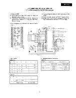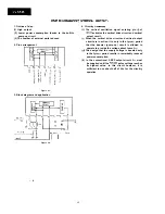
1. Outline of
(3)
(4)
(5)
(7)
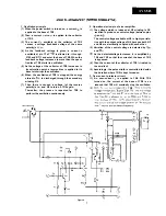
PIF amplifier of sync demodulator type
Negative modulation AGC detector circuit
Tuner RF
AGC
AFC circuit
Video preamplifier
Sound IF amplifier and demodulator circuit
Horizontal oscillator drive circuit/horizontal oscilla-
tor/horizontal output circuit
Audio preamplifier
Horizontal sync circuit with two control loops
Sawtooth wave generator/vertical sync circuit with
automatic
amplitude control cir-
cuit
Sand castle pulse generator circuit
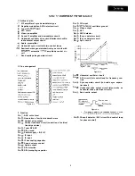
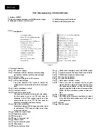
2. Pins arrangement
Figure 2-l.
3. Function
Pin
AGC cut-in level
Pin
Generation of vertical sawtooth wave
Pin
Vertical drive output
Pin
Vertical feedback circuit (correction of vertical
linearity and size)
Pin
Tuner RF AGC
Pin
PIF ground
Pin
Power B (1 IV)
Pin
IF input
Pin
IF input
Pin
IF decoupling capacitor
Pin
Sound volume control
Pin
Audio output
Pin
SIF detection
Pin
SIF decoupling capacitor
Pin
SIF input
Pin
oscillator ground
Pin
Video output
Pin
AFT
Pin
AGC detector
Pin
IF sync detector circuit
Pin
IF sync detector circuit
Pin
Sync circuit
Pin
Pin
Pin
Pin
Pin
I
I
I
I
Figure 2-2.
Horizontal oscillator circuit
AFC circuit (1st control loop for frequency con-
trol)
Sync separator circuit (to decide sync separa-
tion level)
Horizontal drive output circuit (also works as
horizontal drive pulse input circuit.)
Sand castle output
Figure 2-3.
l
Pin
Phase-II detector (APC circuit 2nd control loop
for phase control)
5


