background image

64

E

n

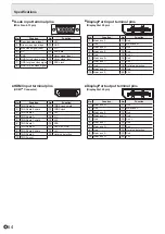
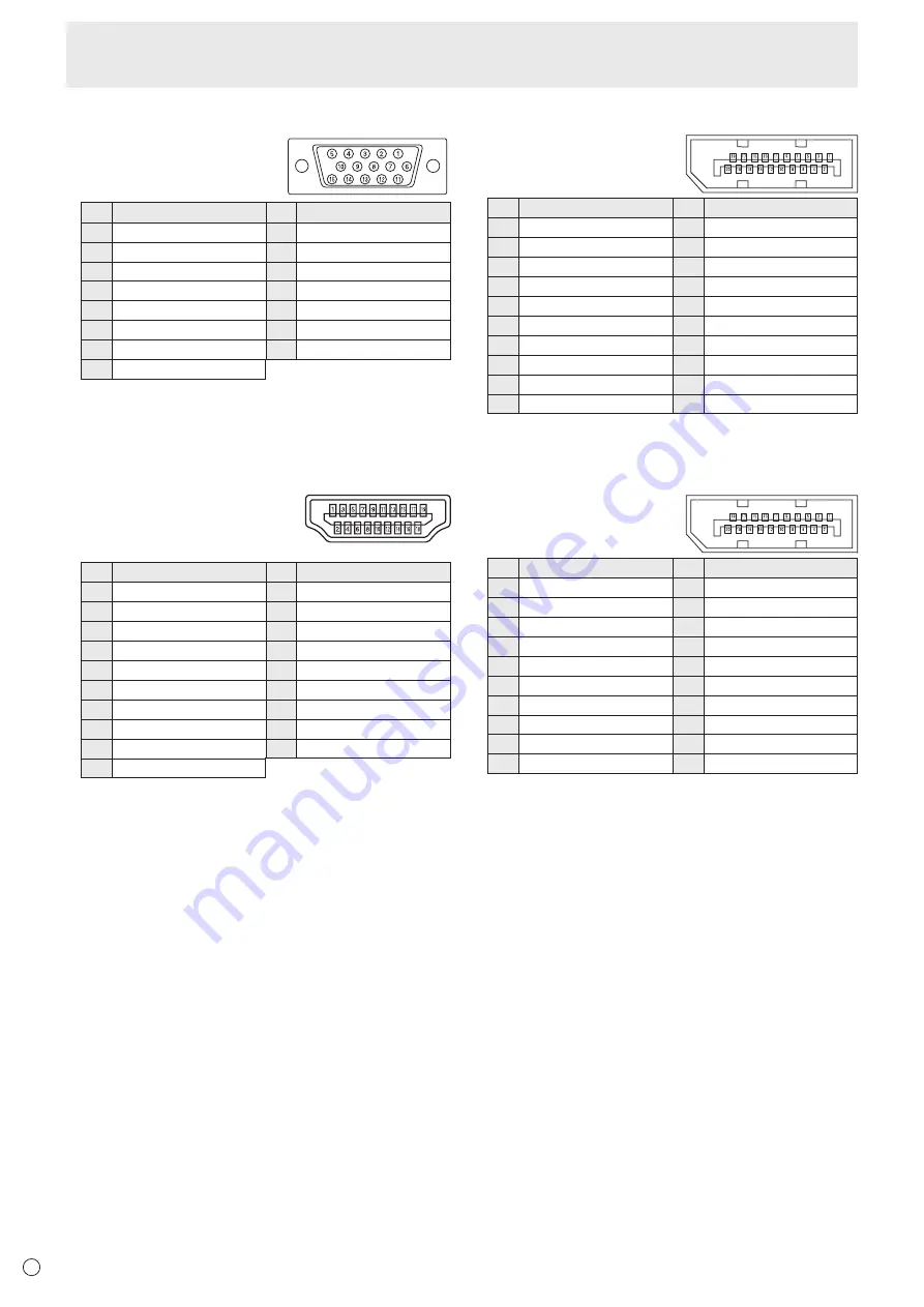
D-sub input terminal pins

(Mini D-sub 15 pin)

No.

Function

No.

Function

1 Red video signal input

9

+5V

2 Green video signal input

10 GND

3 Blue video signal input

11 N.C.

4 N.C.

12 DDC data

5 GND

13 Hsync signal input

6 GND for red video signal

14 Vsync signal input

7 GND for green video signal 15 DDC clock
8 GND for blue video signal

n

HDMI input terminal pins

(HDMI

TM

 Connector)

No.

Function

No.

Function

1

TMDS data 2+

11 TMDS clock shield

2 TMDS data 2 shield

12 TMDS clock-

3 TMDS data 2-

13 CEC

4

TMDS data 1+

14 N.C.

5 TMDS data 1 shield

15 SCL

6 TMDS data 1-

16 SDA

7

TMDS data 0+

17 DDC/CEC GND

8 TMDS data 0 shield

18

+5V

9 TMDS data 0-

19 Hot-plug detection

10

TMDS clock+

n

DisplayPort input terminal pins

(DisplayPort 20 pin)

No.

Function

No.

Function

1 MainLane 3-

11 Gnd 

2 Gnd 

12

MainLane 0+ 

3

MainLane 3+ 

13 Gnd 

4 MainLane 2- 

14 Gnd 

5 Gnd 

15

Aux + 

6

MainLane 2+ 

16 Gnd 

7 MainLane 1-

17 Aux - 

8 Gnd 

18 Hot-plug detection 

9

MainLane 1+ 

19 Gnd 

10 MainLane 0- 

20 3.3V

n

DisplayPort output terminal pins

(DisplayPort 20 pin)

No.

Function

No.

Function

1

MainLane 0+ 

11 Gnd 

2 Gnd 

12 MainLane 3- 

3 MainLane 0- 

13 Gnd 

4

MainLane 1+ 

14 Gnd 

5 Gnd 

15

Aux + 

6 MainLane 1- 

16 Gnd 

7

MainLane 2+ 

17 Aux - 

8 Gnd 

18 Hot-plug detection 

9 MainLane 2- 

19 Gnd 

10

MainLane 3+ 

20 3.3V

Specifications

Содержание aquos PN-L603B

Страница 1: ...PN 70TB3 PN 60TB3 LCD MONITOR OPERATION MANUAL ...

Страница 2: ... dealer and ask for the correct method of disposal ONLY FOR USERS IN THE EUROPEAN UNION AND SOME OTHER COUNTRIES FOR INSTANCE NORWAY AND SWITZERLAND Your participation in separate collection is requested by law The symbol shown above appears on electrical and electronic equipment and batteries or the packaging to remind users of this If Hg or Pb appears below the symbol this means that the battery...

Страница 3: ... literature accompanying the product FOR CUSTOMERS IN U K IMPORTANT The wires in this mains lead are coloured in accordance with the following code GREEN AND YELLOW Earth BLUE Neutral BROWN Live As the colours of the wires in the mains lead of this apparatus may not correspond with the coloured markings identifying the terminals in your plug proceed as follows The wire which is coloured GREEN AND ...

Страница 4: ...hem or objects from resting on them 10 The screen used in this product is made of glass Therefore it can break when the product is dropped or applied with impact Be careful not to be injured by broken glass pieces in case the screen breaks 11 Overloading Do not overload AC outlets or extension cords Overloading can cause fire or electric shock 12 Entering of objects and liquids Never insert an obj...

Страница 5: ... This is a Class A product In a domestic environment this product may cause radio interference in which case the user may be required to take adequate measures To maintain compliance with EMC regulations use shielded cables to connect to the following terminals HDMI input terminal D SUB input terminal and DisplayPort input output terminals If a monitor is not positioned in a sufficiently stable lo...

Страница 6: ...mputer to which the touch panel is connected do not operate the USB device during touch panel input Input may not take place correctly If the infrared transmitter receiver becomes dirty malfunctioning may result Use a soft cloth to gently wipe dirt off the infrared transmitter receiver If dust accumulates inside the infrared transmitter receiver the product cannot transmit or receive infrared rays...

Страница 7: ...ide enough space around the monitor to prevent heat from accumulating inside 7 7 8 20 Unit inch cm 2 5 2 5 2 5 1 7 16 3 5 If it is difficult to provide sufficient space for any reason such as the installation of the monitor inside a housing or if the ambient temperature may be outside of the range of 41 F 5 C to 95 F 35 C install a fan or take other measures to keep the ambient temperature within ...

Страница 8: ... Touch Pen sold separately 19 Touch action 21 Touch action 21 Other functions 23 Cautionary points 23 Eraser 23 Basic Operation 24 Using the touch menu 24 Using the remote control unit 25 Menu Items 27 Displaying the menu screen 27 Menu item details 28 Adjustments for PC screen display 38 Initialization Reset Functional Restriction Setting FUNCTION 39 Controlling the Monitor with a PC LAN 40 Setti...

Страница 9: ...plied CD ROM To install the software see the manual for each To use a touch panel with a computer connected to the bottom connect to the USB 1 port To use a touch panel with a computer connected to the side connect to the USB 2 port Factory setting Can be changed in TOUCH INPUT SELECT in the SETUP menu Liquid Crystal Display Monitor 1 Remote control unit 1 Cable clamp 3 Cable clamp insertion type ...

Страница 10: ...ee page 13 18 Optional terminal This terminal is provided for possible future optional function expansion Offering of this terminal is not a guarantee that future expanded functionality will be provided 19 D sub 1 input terminal See page 12 20 DisplayPort input terminal See page 12 21 HDMI 1 input terminal See page 12 22 Audio 1 input terminal See page 13 23 USB 2 port See page 13 24 D sub 2 input...

Страница 11: ... page 17 3 MUTE button See page 25 4 VOL buttons See page 25 BRIGHT buttons See page 25 Cursor control buttons 5 DISPLAY button See page 25 6 MODE button See page 25 7 INPUT button See page 25 8 MENU button See page 25 9 ENTER button See page 25 10 RETURN button See page 25 11 SIZE button See page 25 ...

Страница 12: ... used in each input mode are factory set as follows Input mode Audio input terminal Factory setting D SUB1 Audio 1 input terminal D SUB2 Audio 2 input terminal DisplayPort DisplayPort input terminal HDMI1 HDMI 1 input terminal HDMI2 HDMI 2 input terminal HDMI3 HDMI 3 input terminal It is convenient to use the terminals for separate purposes For example using the terminal on the bottom of the monit...

Страница 13: ...19 12 USB 1 type B port To use the touch panel with the computer connected to the bottom connect the touch panel to the computer with the USB cable Factory setting Can be changed in TOUCH INPUT SELECT on the SETUP menu 13 USB 2 type B port To use the touch panel with the computer connected to the side connect to the computer with the USB cable Factory setting Can be changed in TOUCH INPUT SELECT i...

Страница 14: ...3 Plug the power cord supplied into the AC power outlet Binding Cables AC input terminal 2 1 Main power switch Power cord Supplied For power outlet 3 Cable Cable clamp insertion type 1 2 1 1 2 1 2 2 2 2 Cable clamp Cable Cable clamp attachment Cable clamp attachment PN 70TB3 only The cables connected to the terminals on the rear of the monitor can be fastened with the cable clamp ...

Страница 15: ...x 16 4 feet 5 m at an angle of approx 10 from the center to the top bottom right left of the remote control sensor 10 10 10 10 Remote control sensor 16 4 feet 5 m TIPS Do not expose the remote control unit to shock by dropping or stepping on it This could lead to a malfunction Do not expose the remote control unit to liquids and do not place it in an area with high humidity The remote control unit...

Страница 16: ...itor Be sure the handles are attached securely 1 2 3 It is possible to mount a commercially available web camera in the following positions Mounting on the tray Attach the web camera to the mounting hole on the right or left side of the tray with the supplied camera screw inch thread x1 Mounting on the top of the monitor 1 Remove the screws from the monitor 2 Attach the supplied camera mount with ...

Страница 17: ...turn the power ON OFF POWER button Power LED Status Status of the monitor Green lit Power on Orange lit Power off Standby mode Green flashing Input signal waiting mode Caution When switching the main power switch or the POWER button off and back on always wait for at least 5 seconds A short interval may result in a malfunction TIPS When the main power switch is off the monitor cannot be turned on ...

Страница 18: ...e time setting screen appears Set the date and time DATE TIME SETTING OK ENTER CANCEL RETURN 01 01 14 00 00 20 1 Press or to select the date and time and press or to change the numerical values 2 Press ENTER Be sure to set the date and time The date time setting screen will close automatically if no operation is performed for about 15 seconds The date and time can be set using DATE TIME SETTING fr...

Страница 19: ...can be registered When active pens are added they can be used to write simultaneously and a different color can be set for each pen To use an active pen with the monitor connect the touch pen adapter to the monitor To use the PN ZL02 with the monitor the active pen must be registered in the touch pen adapter pairing The PN ZL01 is already paired Item Model Remarks Touch pen PN ZL01 Touch pen adapt...

Страница 20: ...be registered in multiple touch pen adapters at once You can affix the supplied ID labels to the PN ZL02 to distinguish the active pens nActive pen actions Pen tip Battery indicator Function button 1 Function button 3 Function button 2 Functions can be assigned to the function buttons For details see the Touch Pen Utility Operation Manual The factory default settings are as follows Function button...

Страница 21: ...t click in some cases TIPS In Windows 7 if the checkmark has been removed from Enable multi touch gestures and inking in Pen and touch in Control Panel select the checkbox For the procedures for using the touch pen in the Pen Software see the Pen Software Operation Manual nCommon finger and touch pen actions Single tap Same action as left clicking a mouse Touch with your finger touch pen Double ta...

Страница 22: ...r finger touch pen and then lift your finger touch pen from the screen Slide to pan With your finger touch pen touching the screen move it up and down to scroll the screen nFinger actions Zoom Use in a screen that is capable of enlargement reduction Touch the screen with two fingers and move your fingers closer together to reduce the view or apart to enlarge the view Reduction Enlargement Press an...

Страница 23: ...ny purpose other than touch panel operation Do not press hard on the pen tip Operation will not take place correctly if there is an obstacle between the infrared transmitter receiver and the touch pen or your finger Operation will not take place correctly if your fingers or your sleeve is near the screen If the touch pen is held too flat against the screen the touch position may not be correctly d...

Страница 24: ...page 31 4 Select the terminal to be used in D SUB1 of INPUT SELECT See page 31 5 Select the terminal for AUDIO SELECT which is used for audio input See page 31 2 Volume adjustment Changes the volume 15 Mutes the sound Touch again to return the sound to the original volume Increases the volume Decreases the volume 3 Touch action setting Touch to disable touch action Touch again to enable touch acti...

Страница 25: ...t press any buttons for about 4 seconds the BRIGHT menu automatically disappears 6 ENTER Confirms the setting 7 RETURN Returns to the previous screen 8 SIZE Screen size selection The menu is displayed Press or to select the screen size See page 26 9 DISPLAY Displays monitor information The display changes from INFORMATION1 INFORMATION2 clear display and so on every time you press this button The d...

Страница 26: ...switching or dual screen display functions to compress or expand the screen for commercial or public viewing in establishments like cafes or hotels may infringe on the rights of the creators as protected by Copyright Law so please be careful When dual screen display is selected the screen size cannot be changed The appearance of the original video may change if you select a screen size with a diff...

Страница 27: ...x 1 0 8 0 V 60 Hz H 67 5 kHz D SUB1 RGB 4 Press or to adjust the setting BRIGHT CONTRAST BLACK LEVEL TINT COLORS SHARPNESS COLOR ADJUSTMENT ADVANCED RESET 31 40 30 30 30 12 SCREEN PICTURE AUDIO SETUP MONITOR PIP PbyP OTHERS PICTURE BACK RETURN MOVE OSD DISPLAY 1 9 2 0 x 1 0 8 0 V 60 Hz H 67 5 kHz D SUB1 RGB For items that have press ENTER make settings and then press RETURN 5 Press MENU to close t...

Страница 28: ...ock phase for applicable video Useful when small characters appear with low contrast and or there are flickers at corners When using the adjustment pattern see page 38 make adjustments so that no horizontal stripe noise appears in it Adjustments to PHASE should be made only after CLOCK has been correctly set H POS Adjust the horizontal position of the image V POS Adjust the vertical position of th...

Страница 29: ...n the WHITE BALANCE is set to PRESET The setting values are shown for reference The color temperature of the screen varies over time This function is not intended to keep the color temperature constant USER Adjusts each item when the WHITE BALANCE is set to USER R CONTRAST Adjusts bright toned red component G CONTRAST Adjusts bright toned green component B CONTRAST Adjusts bright toned blue compon...

Страница 30: ...e RGB input signal range is detected automatically Use AUTO normally If the RGB input signal range cannot be set appropriately even when using AUTO set according to the image When the setting is different images will be displayed with washed out blacks and compressed gradients ACTIVE CONTRAST AV input Automatically adjusts the contrast according to the image In PIP mode the main side setting is re...

Страница 31: ...I3 input terminals D SUB1 Select the input mode to be used in D Sub1 input terminal Select SET after selecting the input mode and then press ENTER HDMI AUTO VIEW When ON is selected the screen size is adjusted automatically according to the screen size control signal included in the video signal input from the AV HDMI input terminal HOT PLUG CONTROL Sets whether to use hot plug control for the HDM...

Страница 32: ...an be used with the computer connected to the USB 1 port When is selected the touch panel cannot be used SIDE USB Sets which input mode the touch panel connected to the USB 2 port is used in Select the terminal into which the video signal of the computer connected to the USB 2 port will be input When SIDE INPUT TERM is selected and the input mode is HDMI2 HDMI3 or D SUB2 the touch panel can be use...

Страница 33: ...n green SELF ADJUST On a D SUB1 RGB D SUB2 screen specify whether to perform screen adjustment automatically or not When ON is selected the screen is automatically adjusted when its resolution is 800 x 600 or higher and the timing of input signals changes ADJUSTING appears on the screen during the adjustment If SELF ADJUST is set to ON set the time it takes to start the SELF ADJUST function in STA...

Страница 34: ... menu item to display the sub screen transparently PIP SOURCE Selects the input signal of the sub screen in PIP PbyP or PbyP2 mode SOUND CHANGE Sets the sound which is output in PIP PbyP or PbyP2 mode If the main screen is displayed as a full screen by the AUTO OFF function the sound for the main screen is output even when the sound for the sub screen is specified MAIN POS Sets the position of the...

Страница 35: ...ELECT PRIORITY Sets the order of input terminal priority for NO SIGNAL AUTO INPUT SEL Input does not change automatically for terminals without a priority setting LOGO SCREEN Sets whether or not to display the logo screen INPUT SIGNAL D SUB1 RGB D SUB2 If the resolution of the computer is one of the following make a selection from the following options 480 LINES AUTO 640x480 or 848x480 768 LINES A...

Страница 36: ... displayed in NORMAL size except when it is set as the PIP main screen When dual screen display is selected the SCREEN MOTION function is disabled When dual screen display is selected the CONNECT AUTO INPUT SELECT function and NO SIGNAL AUTO INPUT SEL function are disabled When dual screen display is selected the INPUT SELECT options cannot be set When dual screen display is selected the AUDIO men...

Страница 37: ...RY DAY Executes the SCHEDULE every day regardless of the day of the week 4 TIME Specifies the time to execute the SCHEDULE Set the time on a 24 hour basis Factory default Can be entered as 12 hour time using the TIME setting in DATE TIME FORMAT 5 INPUT Specifies the input mode at power on If you don t specify this the input active at the last power off will appear Input modes displayed on HDMI1 HD...

Страница 38: ... adjustment Before making adjustments in the SCREEN menu or PICTURE menu display an image to brighten the entire screen If you are using a Windows PC use the adjustment pattern on the supplied CD ROM Opening the adjustment pattern The following example is performed in Windows 7 1 Load the supplied CD ROM into the computer s CD ROM drive 2 Open CD Drive in Computer 3 Double click Adj_uty exe in the...

Страница 39: ... Functional Restriction Setting FUNCTION OSD DISPLAY Shows hides the menu modes and messages The FUNCTION screen cannot be hidden ON 1 Shows all menus modes and messages ON 2 Hides messages automatically displayed by the display Shows messages during operation OFF Hides all menus modes and messages LED Specifies whether to light the power LED TEMPERATURE ALERT Selects the notification method for a...

Страница 40: ...l not initialize e mail addresses and other settings Controlling the Monitor with a PC LAN Settings to connect to a LAN Set the monitor s IP address and subnet mask to match the settings of your LAN These settings can be made on either the monitor or a PC connected to the monitor The settings depend on the configuration of your LAN Ask your LAN administrator for details To set on the monitor Set t...

Страница 41: ...roperties 5 Click Internet Protocol Version 4 TCP IPv4 and then Properties 6 Make a note of the current IP address subnet mask and default gateway settings Make sure you write this information now as you will be changing the IP address subnet mask and default gateway settings back to these settings afterwards 7 Temporarily change the IP address and subnet mask To access the monitor as it is shippe...

Страница 42: ... set a USER NAME and PASSWORD Basic operation You use Internet Explorer on a PC on the LAN to control the monitor 1 Launch Internet Explorer on the PC 2 In the Address box type http followed by your monitor s IP address followed by then press the Enter key You can confirm the IP address with the DISPLAY function When prompted to enter a user name and password type the user name and password that y...

Страница 43: ...JUSTMENT You can adjust these settings which are also available on the monitor s menu SCREEN See page 28 PICTURE See pages 29 to 30 AUDIO See page 31 SETUP See pages 31 to 32 MONITOR See page 33 SCHEDULE See page 37 PIP PbyP See page 34 OTHERS See page 35 FUNCTION See page 39 TIPS After changing DISPLAY COLOR PATTERN to OFF in PICTURE menu click Refresh to correctly retrieve the status of the moni...

Страница 44: ...using a DNS server specify 0 0 0 0 RESET Clicking Execute returns all of the LAN SETUP settings to the factory preset values except for the DNS SERVER ADDRESS AUTO ACQUISITION and DNS SERVER settings NETWORK SECURITY This screen allows you to specify the security related settings USER NAME PASSWORD Sets up a user name and password to restrict access to this monitor After entering a user name and p...

Страница 45: ...s screen allows you to configure the e mail sent periodically or when the monitor has an error The settings depend on the configuration of your LAN Ask your LAN administrator for details SMTP SERVER Specify the SMTP server address for sending e mail When using a domain name make sure to specify the DNS server as well See page 44 SMTP PORT If the AUTHENTICATION is SMTP AUTH specify the port number ...

Страница 46: ...il which notifies a temperature or status error TIPS The RECIPIENT E MAIL ADDRESSES can be up to 64 alphanumeric characters or symbols Controlling the Monitor with a PC LAN MAIL PERIODICAL When PERIODICAL for CONDITION of MAIL RECIPIENT is checked set the date and time to send the mail DAY OF THE WEEK Specify the day of the week to send the periodical mails TIME Specify the time of the day to send...

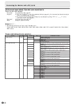
Страница 47: ...turn it on again with the main power switch When the monitor restarts wait about 30 seconds and then start the next operation If the IP address is changed while the SNMP function is operational turn off the monitor and then turn it on again with the main power switch TIPS Depending on the SNMP settings a short delay may occur before the SNMP is usable About 5 minutes Up to 16 alphanumeric letters ...

Страница 48: ...with the monitor and quit the function 1 Send BYE When the transmission is successful goodbye is returned and the connection is disconnected TIPS Connection is automatically disconnected when the time specified in AUTO LOGOUT TIME elapses over a no communication period Advanced operation Communication procedure nCommand format When a command is sent from the PC to the monitor the monitor operates ...

Страница 49: ... used WAIT is returned In this case a value will be returned if you wait a while Do not send any command during this period Commands which return WAIT RSET INPS ASNC WIDE PXSL POWR AGIN MWIN MWIP MWPP TIPS If the processing takes time WAIT may be returned multiple times When control via LAN is locked to prevent use using the operation lock function see page 39 E C D K O L Return code 0DH 0AH nComm...

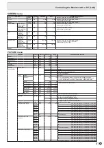
Страница 50: ... Normal mode 2 Input signal waiting mode INPUT MODE SELECTION INPS W 0 Toggle change for input mode Terminals not selected in INPUT SELECT cannot be selected 2 D SUB1 RGB ERR when other than RGB is selected for D SUB1 of INPUT SELECT 3 D SUB1 COMPONENT ERR when other than COMPONENT is selected for D SUB1 of INPUT SELECT 4 D SUB1 VIDEO ERR when other than VIDEO is selected for D SUB1 of INPUT SELEC...

Страница 51: ... WR 0 256 0 256 R OFFSET OFSR WR 127 127 127 127 G OFFSET OFSG WR 127 127 127 127 B OFFSET OFSB WR 127 127 127 127 COPY TO USER CPTU W 0 Copies a preset value to the user setting GAMMA GAMM WR 0 2 0 2 0 1 8 1 2 2 2 2 4 during PC input 0 LIGHT 2 2 DARK during AV input 4 6 4 6 4 USER 5 2 0 6 STD during PC input 4 USER 5 LIGHT 1 6 STD during AV input FLESH TONE AV input FLES WR 0 2 0 2 0 OFF 1 LOW 2 ...

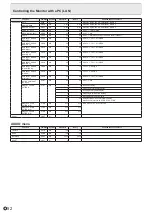
Страница 52: ... RGB INPUT RANGE HDMI3 PC PH3R WR 0 2 0 2 0 AUTO 1 FULL 2 LIMITED RGB INPUT RANGE D SUB1 RGB PDSR WR 1 2 1 2 1 FULL 2 LIMITED RGB INPUT RANGE D SUB2 PD2R WR 1 2 1 2 1 FULL 2 LIMITED RGB INPUT RANGE DisplayPort PDPR WR 0 2 0 2 0 AUTO 1 FULL 2 LIMITED ACTIVE CONTRAST AV input ACNT WR 0 1 0 1 0 OFF 1 ON DISPLAY COLOR PATTERN PTDF WR 0 0 No pattern display 1 1 White single color pattern display 2 2 Re...

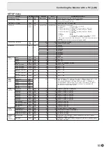
Страница 53: ...CH WR 0 1 0 1 0 OFF 1 ON HOT PLUG CONTROL HDMI2 HPH2 WR 0 1 0 1 0 OFF 1 ON HOT PLUG CONTROL HDMI3 HPH3 WR 0 1 0 1 0 OFF 1 ON INPUT MODE NAME DisplayPort INDP WR 0 30 0 30 0 NO SETTING 1 PC1 2 PC2 3 PC3 4 TV 5 VIDEO 6 DVD 7 HDD 8 DVR 9 BD 10 CAMERA 11 DOCUMENT CAMERA 12 VIDEO CAMERA 13 VIDEO CONFERENCE 14 GAME 15 VGA 16 BNC 17 COMPOSITE 18 COMPONENT 19 RGB 20 INPUT1 21 INPUT2 22 INPUT3 23 INPUT4 24...

Страница 54: ...t connected ERR when Touch Panel Settings Tool is installed in the computer connected to the touch panel TOUCH PANEL MODE GMDP WR 0 1 0 1 0 OFF 1 ON When the input mode is PC PIP PbyP menu Function Command Direction Parameter Reply Control Response contents PIP MODES MWIN WR 0 3 0 3 0 OFF 1 PIP 2 PbyP 3 PbyP2 PIP SIZE MPSZ WR 1 64 1 64 PIP POS The longest direction MHPS WR 0 100 0 100 The shortest...

Страница 55: ...elected for NO SIGNAL AUTO INPUT SEL All input terminals cannot be set to 0 simultaneously HDMI1 APH1 HDMI2 APH2 HDMI3 APH3 D SUB1 APD1 D SUB2 APD2 LOGO SCREEN BTSC WR 0 1 0 1 0 OFF 1 ON INPUT RESOLUTION PC RESOLUTION CHECK PXCK R Returns current resolution in the form of hhh vvv PIXEL SETTING D SUB1 RGB D SUB2 PXSL WR 1 1 768 1360 x 768 2 2 768 1280 x 768 3 3 768 1024 x 768 5 5 480 848 x 480 6 6 ...

Страница 56: ...Toggle to change size 1 WIDE 2 ZOOM1 3 ZOOM2 4 NORMAL 5 Dot by Dot VOLUME VOLM WR 0 31 0 31 MUTE MUTE WR 0 1 0 1 0 OFF 1 ON INFORMATION MODEL INF1 R Value SERIAL NO SRNO R Value TEMPERATURE SENSOR DSTA R 0 Internal temperature normal 1 Internal temperature abnormal has occurred and the monitor is in standby mode 2 Internal temperature abnormal occurred To delete the information of temperature abno...

Страница 57: ...consists of 4 digits If data is less than 4 digits add a 0 zero to make it 4 digits The checksum field is the character string ASCII data of lower order one byte which indicates the sum of the block number and 32 pieces of data in hexadecimal 0 to F Saving the GAMMA user data Use the user data save command UGSV to save the transferred user data in the monitor If the data is not saved it will be cl...

Страница 58: ...e DisplayPort standard compliant The monitor will not work with cables that are not standard compliant Control buttons do not work There is no picture Load noises from outside may be interfering with normal operation Turn off the power and turn it on after waiting at least 5 seconds and then check the operation The input mode changes automatically When CONNECT AUTO INPUT SELECT is ON the input mod...

Страница 59: ...utomatically in order to prevent high temperature related problems When this occurs TEMPERATURE is displayed on the screen and the Power LED flashes red and green alternately When TEMPERATURE ALERT is set to OSD LED This varies depending on the setting If the internal temperature rises further the monitor automatically enters standby mode The Power LED continues flashing red and green alternately ...

Страница 60: ...ter port USB 2 0 compliant Type A Power requirement AC 100 V 240 V 2 6 A 50 60 Hz AC 100 V 240 V 2 2 A 50 60 Hz Operating temperature 2 3 41 F to 95 F 5 C to 35 C Operating humidity 3 20 to 80 no condensation Power consumption Maximum input signal waiting mode 4 standby mode 5 225 W 14 W 3 5 W 185 W 14 W 3 5 W Dimensions excluding protrusions inch mm Approx 64 13 16 W x 3 11 16 D x 39 3 4 H 1647 x...

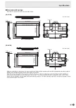
Страница 61: ... 7 7 8 200 3 11 16 94 1 15 16 49 Unit inch mm Unit inch mm PN 60TB3 PN 70TB3 When mounting the monitor be sure to use a wall mount bracket that complies with the VESA compatible mounting method SHARP recommends using M6 screws and tighten the screws Note that screw hole depth of the monitor is 3 8 inch 10 mm Loose mounting may cause the product to fall resulting in serious personal injuries as wel...

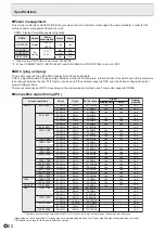
Страница 62: ...1600 1000 31 5kHz 37 9kHz 37 5kHz 35 1kHz 37 9kHz 48 1kHz 46 9kHz 31 0kHz 48 4kHz 56 5kHz 60 0kHz 67 5kHz 47 8kHz 60 3kHz 49 7kHz 60 0kHz 64 0kHz 80 0kHz 47 7kHz 65 3kHz 55 9kHz 75 0kHz 65 3kHz 74 0kHz 44 7kHz 67 5kHz 31 5kHz 48 3kHz 53 6kHz 56 6kHz 61 8kHz 71 8kHz 71 7kHz 81 1kHz 68 6kHz 60Hz 72Hz 75Hz 56Hz 60Hz 72Hz 75Hz 60Hz 60Hz 70Hz 75Hz 75Hz 60Hz 75Hz 60Hz 60Hz 60Hz 75Hz 60Hz 60Hz 60Hz 60Hz ...

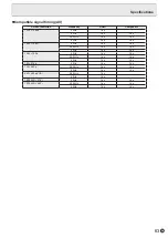
Страница 63: ...59 94Hz Yes Yes 60Hz Yes Yes 1920 1080i 50Hz Yes Yes 59 94Hz Yes Yes 60Hz Yes Yes 1280 720p 50Hz Yes Yes 59 94Hz Yes Yes 60Hz Yes Yes 720 576p 50Hz Yes Yes 720 480p 59 94Hz Yes Yes 60Hz Yes Yes 640 480p VGA 59 94Hz Yes 60Hz Yes 720 1440 576i 50Hz Yes Yes 720 1440 480i 59 94Hz Yes Yes 60Hz Yes Yes Specifications ...

Страница 64: ... data 1 shield 15 SCL 6 TMDS data 1 16 SDA 7 TMDS data 0 17 DDC CEC GND 8 TMDS data 0 shield 18 5V 9 TMDS data 0 19 Hot plug detection 10 TMDS clock nDisplayPort input terminal pins DisplayPort 20 pin No Function No Function 1 MainLane 3 11 Gnd 2 Gnd 12 MainLane 0 3 MainLane 3 13 Gnd 4 MainLane 2 14 Gnd 5 Gnd 15 Aux 6 MainLane 2 16 Gnd 7 MainLane 1 17 Aux 8 Gnd 18 Hot plug detection 9 MainLane 1 1...

Страница 65: ...ll which can endure at least 4 times or more the weight of the monitor Install by the most suitable method for the material and the structure To attach a VESA compliant mounting bracket use M6 screws that are 5 16 inch 8 mm to 3 8 inch 10 mm longer than the thickness of the mounting bracket Do not use an impact driver After mounting please carefully ensure the monitor is secure and not able to com...

Страница 66: ...PN 70TB3 60TB3 M EN14C 1 ...

Отзывы: