background image

LC-42BT10U

12

NO.

PARTS CODE

PRICE 

RANK

NEW 

MARK

PART 

DELIVERY

DESCRIPTION

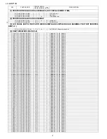
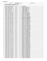
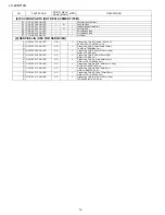
[8] PACKING PARTS (NOT REPLACEMENT ITEM)

S1

SPAKCD085WJZZ

-

-

Packing Case (Bottom)

S2

SPAKCD592WJZZ

-

N

-

Packing Case

S3

SPAKPA774WJZZ

-

-

Wrapping Paper (Monitor)

S4

SPAKXB560WJZZ

-

N

-

Packing Add.

S5

SSAKA0101GJZZ

-

-

Polyethylene Bag

S6

SSAKAA032WJZZ

-

-

Polyethylene Bag

S7

TLABKA009WJZZ

-

-

No. Label

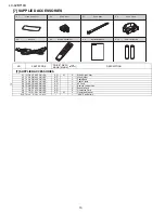
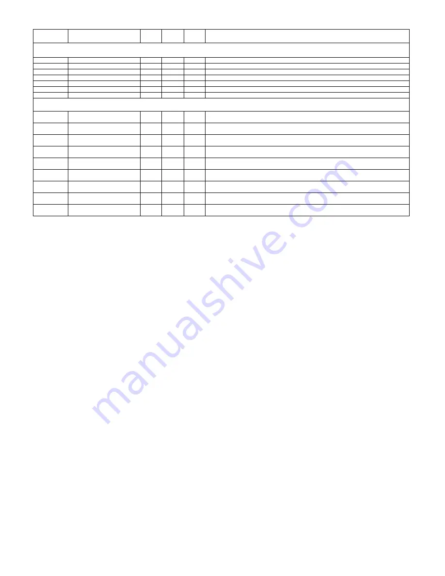
[9] SERVICE JIG (USE FOR SERVICING)

N

QCNW-C222WJQZ

AW

J

Connecting Cord (FFC 80pin 100cm), x2

N

PANEL to LCD CONTROL Unit

N

QCNW-C799WJPZ

AG

J

Connecting Cord (Coaxial Cable 100cm)

N

TUNER to TERMINAL Unit

N

QCNW-D483WJQZ

AX

J

Connecting Cord (PH 12pin 100cm 12pin)

N

MAIN to POWER Unit

N

QCNW-E068WJQZ

AS

J

Connecting Cord (PD 6pin 100cm 6pin)

N

MAIN to POWER Unit

N

QCNW-E134WJQZ

BG

J

Connecting Cord (LV 41pin 40cm 41pin)

N

MAIN to LCD CONTROL Unit

N

QCNW-F135WJQZ

AS

J

Connecting Cord (LA 6pin 100cm 3pin + 3pin)

N

POWER to INVERTER Unit

N

QCNW-F136WJQZ

AP

J

Connecting Cord (LB 4pin 100cm 9pin)

N

MAIN to INVERTER Unit

N

QCNW-F137WJQZ

AX

J

Connecting Cord (LP 20pin 100cm 20pin)

N

MAIN to LCD CONTROL Unit

N

QCNW-F139WJQZ

AX

J

Connecting Cord (RA 13pin 100cm 13pin)

N

TERMINAL to R/C, LED Unit

Содержание Aquos LC-42BT10U

Страница 1: ... 1 CHAPTER 2 OPERATION MANUAL 1 OPERATION MANUAL 2 1 CHAPTER 3 DIMENSIONS 1 DIMENSIONS 3 1 CHAPTER 4 REMOVING OF MAJOR PARTS 1 REMOVING OF MAJOR PARTS 4 1 CHAPTER 5 OVERALL WIRING BLOCK DIAGRAM 1 OVERALL WIRING DIAGRAM 5 1 2 SYSTEM BLOCK DIAGRAM 5 3 CHAPTER 6 SCHEMATIC DIAGRAM 1 DESCRIPTION OF SCHEMATIC DIAGRAM 6 1 2 TERMINAL Unit 6 2 Parts Guide TopPage CONTENTS In the interests of user safety Re...

Страница 2: ... KZA510WJPZY RC KZA237WJZZY Change C1553 Capacitor 10 16V Ceramic RC KZA510WJPZY RC KZA237WJZZY Change C1556 Capacitor 10 16V Ceramic RC KZA510WJPZY RC KZA237WJZZY Change C1566 Capacitor 10 16V Ceramic RC KZA510WJPZY RC KZA237WJZZY Change C1575 Capacitor 10 16V Ceramic RC KZA510WJPZY RC KZA237WJZZY Change C1577 Capacitor 10 16V Ceramic RC KZA510WJPZY RC KZA237WJZZY Change C1585 Capacitor 10 16V Ce...

Страница 3: ...ramic RC KZA510WJPZY RC KZA237WJZZY Change C9649 Capacitor 10 16V Ceramic RC KZA510WJPZY RC KZA237WJZZY Change C9652 Capacitor 10 16V Ceramic RC KZA510WJPZY RC KZA237WJZZY Change C9653 Capacitor 10 16V Ceramic RC KZA510WJPZY RC KZA237WJZZY Change C9654 Capacitor 10 16V Ceramic RC KZA510WJPZY RC KZA237WJZZY Change C9655 Capacitor 10 16V Ceramic RC KZA510WJPZY RC KZA237WJZZY Change C9707 Capacitor 1...

Страница 4: ...Change R8329 Resistor 22 1 16W Metal Oxide VRK CD1JJ220JY VRS CK1JF220JY Change R8330 Resistor 22 1 16W Metal Oxide VRK CD1JJ220JY VRS CK1JF220JY Change R8331 Resistor 22 1 16W Metal Oxide VRK CD1JJ220JY VRS CK1JF220JY Change R8333 Resistor 150 1 16W Metal Oxide VRK CD1JJ151JY VRS CK1JF151JY Change R8334 Resistor 150 1 16W Metal Oxide VRK CD1JJ151JY VRS CK1JF151JY Change R8335 Resistor 150 1 16W M...

Страница 5: ...he resistor All checks must be repeated with the AC cord plug connection reversed If necessary a nonpolarized adaptor plug must be used only for the purpose of completing these checks Any reading of 0 75 Vrms this corresponds to 0 5 mA rms AC or more is excessive and indicates a potential shock hazard which must be corrected before returning the monitor to the owner SAFETY NOTICE Many electrical a...

Страница 6: ...éseaux de résistancecapacité les isolateurs mécaniques etc S assurer qu il n y ait pas de danger d électrocution en vérifiant la fuite de courant de la facon suivante Brancher le cordon d alimentation directem ent à une prise de cou rant de 120V Ne pas utiliser de transformateur d isolation pour cet essai A l aide de deux fils à pinces brancher une résistance de 1 5 kΩ 10 watts en parallèle avec u...

Страница 7: ...solder by 40 C and as it has poor solder wettability you may be apt to keep the soldering bit in contact with the PWB for extended period of time However Since the land may be peeled off or the maximum heat resistance temperature of parts may be exceeded remove the bit from the PWB as soon as you confirm the steady soldering condition Lead free solder contains more tin and the end of the soldering...

Страница 8: ...tection management measures 1 When disposing of the component parts and PWBs destruct the IC itself in a proper way For repairing or replacing the component parts and PWBs as well as clearing those in stock 2 In storing the component parts protect and manage them against theft and disclosure For storing the service parts service units etc Applied part HDCP KEY ROM IC8451 RH IXB963WJQZQ updated ROM...

Страница 9: ...Emergency alert messages via Cable are unreceivable 2 The dimensional drawings are shown on the inside back cover As part of policy of continuous improvement SHARP reserves the right to make design and specification changes for product improvement without prior notice The performance specification figures indicated are nominal values of production units There may be some deviations from these valu...

Страница 10: ...cal Picture Control SLEEP indicator TV Rear Top POWER button Channel buttons CH Volume buttons VOL INPUT button HDMI terminal INPUT 4 INPUT 3 terminals AUDIO OUTPUT terminals HDMI terminal INPUT 5 DIGITAL AUDIO OUTPUT terminal Antenna Cable in INPUT 1 terminals AC INPUT terminal AUDIO terminals INPUT 4 INPUT 2 terminals DVI I terminal INPUT 6 AUDIO terminal INPUT 6 RS 232C terminal ...

Страница 11: ...he same time 15 LIGHT When pressed all buttons on the remote control unit will light The lighting will turn off if no operations are performed within about 5 seconds This button is used for performing operations in low light situations 16 VIEW MODE Select the screen size 17 ENT Jumps to a channel after selecting with the 0_9 buttons 18 FLASHBACK Return to the previous channel or external input mod...

Страница 12: ...tallation and may cause serious injuries Installing the TV requires special skill that should only be performed by qualified service personnel Customers should not attempt to do the work themselves SHARP bears no responsibility for improper mounting or mounting that results in accident or injury Using a SHARP recommended bracket to mount the TV You can ask a qualified service professional about us...

Страница 13: ...The picture may look dark in a room that is too bright Check the input signal setting Is the sleep timer set Check the power control settings The unit s internal temperature has increased Remove any objects blocking vent or clean Is connection to other components correct Is correct input signal source selected after connection Is the correct input selected Is picture adjustment correct Is On selec...

Страница 14: ...75 Hz 56 Hz 60 Hz 72 Hz 75 Hz 60 Hz 70 Hz 75 Hz 60 Hz 60 Hz O O O O O O O O O O O O 64 0 kHz SXGA 1400 x 1050 60 Hz O 75 0 kHz UXGA 1600 x 1200 60 Hz O DDC is a registered trademark of Video Electronics Standards Association Power Management is a registered trademark of Sun Microsystems Inc VGA and XGA are registered trademarks of International Business Machines Co Inc PC Horizontal Frequency VESA...

Страница 15: ...olor Tint Sharpness Advanced Color Temp Black Fine Motion Monochrome Film Mode Range of OPC Reset Treble Bass Balance Surround Reset No Signal Off No Operation Off EZ Setup CH Setup Antenna Setup DIGITAL Input Skip Input Label Parental CTRL Position Language Reset Audio Only Digital Noise Reduction Input Select Output Select Color System Caption Setup Program Title Display Favorite CH Audio Setup ...

Страница 16: ...LC 42BT10U 3 1 LC 42BT10U Service Manual CHAPTER 3 DIMENSIONS 1 DIMENSIONS 77 8 200 4019 32 1031 3647 64 933 0 16 37 64 421 20 23 32 526 0 59 32 134 26 37 64 675 7 7 8 200 3 23 64 85 Unit inch mm ...

Страница 17: ... Manual CHAPTER 4 REMOVING OF MAJOR PARTS 1 REMOVING OF MAJOR PARTS 1 Remove the SD Card Cover 2 Remove the Hole Cover 3 Remove the 12 lock screws 5 lock screws and detach the Rear Cabinet 3 2 3 Rear Cabinet Hole Cover SD Card Cover 1 ...

Страница 18: ...ck screws and detach the Stand Assist Angle 7 Remove the 2 lock screws and detach the Stand Assist Cover 8 Remove the 4 lock screws and detach the Stand Fixing Angle 9 Remove the 7 lock screws and detach the MAIN Shield 9 5 5 8 6 4 4 7 Center Angle L MAIN Shield Center Angle R Stand Fixing Angle Chassis Fixing Angle Stand Assist Cover Stand Assist Angle ...

Страница 19: ... all the PWBs 11 Remove the Top Cover Ass y Remove the 1 lock screw from the Top Cover Ass y and detach the KEY Unit 䬌䎮䎰䬍 䬌䎵䎤䬍 䬌䎳䎧䬍 䬌䎰䎤䬍 䬌䎵䎤䬍 䬌䎯䎹䬍 䬌䎮䎰䬍 䬌䎩䎦䬍䬌䎶䎤䬍 䬌䎳䎫䬍 䬌䎯䎥䬍 䬌䎯䎳䬍 䬌䎦䎱䎖䬍 䬌䎳䎧䬍 䬌䎳䎫䬍 䬌䎶䎳䬍 䬌䎯䎤䬍 䬌䎦䎱䎕䬍 䬌䎯䎤䬍 䬌䎯䎥䬍 11 10 10 10 Top Cover Ass y KEY Unit ...

Страница 20: ... RS232C Angle and TERMINAL Unit 16 Remove the 3 lock screws 2 lock screws 1 lock rivet and detach the MAIN PWB Radiator and MAIN Unit 17 Remove the 1 lock rivet and detach the Earth Plate 18 Remove the 2 lock screws and detach the Speaker L R 19 Remove the 2 lock screws and detach the R C LED Unit R C LED Unit 16 16 16 17 14 12 13 13 13 13 15 15 18 18 19 Speaker R TERMINAL Unit RS232C Angle Tray C...

Страница 21: ...ngle Top L R 21 Remove the 3 lock screws and detach the Lug Angle Top Center 22 Remove the 9 lock screws and detach the Lug Angle Bottom 23 Remove the LCD Panel Module 20 20 20 20 21 21 Lug Angle Top R Lug Angle Top Center Lug Angle Bottom Lug Angle Top L 22 22 22 ...

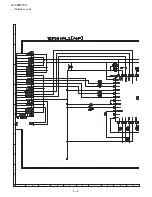
Страница 22: ...㪛㪠㪦 㪦㪧㪫㪠㪚㪘㪣 㪦㪬㪫㪧㪬㪫 㪛䊶㪘 㵘 㪫㪬㪥㪜㪩 㪫㫉㫀㪻㪼㫅㫋 㪣㪯 㪪㪜㪠㪥㪜 㪘㪫㪠 㪈 㪉㪇 㪘㪭㪄㪪㪮 㪘㪤㪧 㪚㫆㫄㫇㫆㫅㪼㫅㫋㪆㪚㫆㫄㫇㫆㫊㫀㫋 㪈㪊 㪈㩷㩷㪋 䇼㪤㪘䇽 䇼㪝㪚䇽 䇼㪪㪘䇽 䇼㪤㪘䇽 䇼㪝㪚䇽 䇼㪪㪘䇽 䇼㪢㪤䇽 䇼㪧㪛䇽 䇼㪧㪟䇽 䇼㪣㪙䇽 䇼㪝㪛䇽 䇼㪣㪭䇽 䇼㪝㪘䇽 䇼㪣㪧䇽 䇼㪩㪘䇽 䇼㪩㪘䇽 䇼㪢㪤䇽 䇼㪪㪧䇽 㪋㪉㩹㪣㪚㪛㩷㪧㪸㫅㪼㫃 㪈㪐㪉㪇㬍㪈㪇㪏㪇 䇼㪪㪣䇽 䇼㪪㪩䇽 㪫㪜㪩㪤㪠㪥㪘㪣 㪛㪐㪊㪌 㪈 㪈 㪪 㪍 㪈 㪈 㪈㪉 㪈 㪋 㪈 㪌 㪈 㪋 㪨㪧㪮㪙㪟㪛㪏㪊㪏㪮㪡㪨㪱 㪨㪚㪥㪮㪄㪜㪈㪊㪋㪮㪡㪨㪱㩿㪪㪼㫉㫍㫀㪺㪼㪀 㪚㫆㫄㫇㫆㫅㪼㫅㫋㪆㪚㫆㫄㫇㫆㫊㫀㫋 㪨㪚㪥㪮㪄㪜㪏㪐㪏㪮㪡㪨㪱 㪨㪚㪥㪮㪄㪝㪈㪊㪍㪮㪡㪨㪱㩿㪪㪼㫉㫍㫀㪺㪼㪀 㪨㪚㪥㪮㪄㪝㪇㪈㪏㪮㪡㪨㪱 㪨㪚㪥㪮㪄㪝㪈㪊㪐㪮㪡㪨㪱㩿㪪㪼㫉㫍㫀㪺㪼㪀 㪨㪚㪥㪮㪄㪜㪏㪐㪎㪮㪡㪨...

Страница 23: ... 㪉 㪠㪥㪭㪄㪈㵘 㪬㪥㪠㪫 㪈 㪉 㪈 㪉 㪈 㪉 㪈 㪉 㪈 㪉 㪈 㪊 㪧㪦㪮㪜㪩㵘 㪬㪥㪠㪫 㪩㪛㪜㪥㪚㪘㪈㪏㪋㪮㪡㪨㪱 㪍 㪈 㪍 㪈 㪣㪚㪛㩷㪚㫆㫅㫋㵘 㪬㪥㪠㪫 㪏㪇 㪈 㪚㪥㪊 㪇㪅㪌㪪㪣㩷㪥㪘㪉㪉㪉 㪏㪇 㪚㪥㪋 㪅㪌㪪㪣㩷㪥㪘㪉㪉㪉 㪋㪈 㪈 㪚㪥㪊 㪠㪚㪈 㪠㪚㪉 㪈 㪈㪉 䇼㪣㪘䇽 䇼㪧㪟䇽 䇼㪧㪛䇽 㪋㪉㩹㪣㪚㪛㩷㪧㪸㫅㪼㫃 㪈㪐㪉㪇㬍㪈㪇㪏㪇 䇼㪣㪘䇽 㪼㪀 㪺㪼㪀 㪜㪐㪇㪉㪮㪡㪨㪱 㪛㪋㪏㪊㪮㪡㪨㪱㩿㪪㪼㫉㫍㫀㪺㪼㪀 㪮㪄㪜㪉㪌㪏㪮㪡㪨㪱 㪮㪄㪜㪇㪍㪏㪮㪡㪨㪱㩿㪪㪼㫉㫍㫀㪺㪼㪀 㪨㪚㪥㪮㪄㪝㪈㪋㪈㪮㪡㪨㪱 㪨㪚㪥㪮㪄㪝㪈㪊㪌㪮㪡㪨㪱㩿㪪㪼㫉㫍㫀㪺㪼㪀㪧 㪐 㪈 䇼㪣㪙䇽 ...

Страница 24: ...8 5 4 QORQPGPV WFKQ 0276 0276 0276 0276 0276 8 4 8 4 WFKQ 8 0 4 5 6 241 4 5 6 A GP VCN 68A52 68A 5 2 94 6 0 51 69 4 14 100 614 A 4 2 8 A 1 8 8 8 8 5 0 670 4A8 0 5 2 0 8 5 4 8 2D2T 2D2T 8 8 8 䇼MA䇽 SC502 SC1102 23PIN 8 VQ 0 㪠㪚㪉㪎㪇㪈 㪘㫌㪻㫀㫆㩷㪘㪤㪧 㪫㪧㪘㪊㪈㪇㪇 2 8 8 8 6Q 2 4 4GUGV 6 KIKVCN 0 68 78 DKV 8 8 8 241 MDKV 8 8 8 2 100 614 14 2 䇼FC䇽䋺 SC501 SC1101 23PIN䋩 䇼SA䇽䋺㩷P2704 SC1301 23PIN䋩 䇼㪪㪧䇽 㪧㪉㪎㪇㪊 㪜㪯㪫㪄㪪㪧 52 4 ...

Страница 25: ...UUGT VCN 8 5 176 4 DKV 8 27 7 46 2 94 6 0 51 69 4 7 614 14 100 614 7 8 4 7 6 2 1 5A5 6 41 5 VCN 219 4 5722 4 7 6 0 5 56 8 8 8 8 8 8 8 8 8 GVE 7 8 241 A5 5 9 2 08A 44 241 4 6A20 8 6A 8 GVE 1 56 A219 ޣ ޤ RKP 2 1 1 1 ޣ 5 ޤ 2 RKP A 6 8DTV 7 1 1 1 6 4 1 12 06 4 1 8 A A 59 8 2 8 72 5 56 7 8 7 8 2 A4 3 1 A219 45A10 0 A219 54 5 6 1165 1 1 5 6 ޣ 4 ޤ 2 R 6 417 74 8 㧔20 X㧕 7 8 ޣ 2 ޤ 219 4 106 2 2 0 7 46 7 46...

Страница 26: ...LC 42BT10U 5 5 MEMO ...

Страница 27: ...F unless otherwise noted P pF µµF 2 All capacitors are 50V unless otherwise noted CAUTION This circuit diagram is original one therefore there may be a slight difference from yours SAFETY NOTES 1 DISCONNECT THE AC PLUG FROM THE AC OUTLET BEFORE REPLACING PARTS 2 SEMICONDUCTOR HEAT SINKS SHOULD BE REGARDED AS POTENTIAL SHOCK HAZARDS WHEN THE CHASSIS IS OPERATING IMPORTANT SAFETY NOTICE PARTS MARKED...

Страница 28: ...LC 42BT10U 6 2 2 TERMINAL Unit TERMINAL Unit 1 2 A C B D E F G H 1 2 3 4 5 6 7 8 9 10 DUNTKD935FM12 ...

Страница 29: ...LC 42BT10U 6 3 10 11 12 13 14 15 16 17 18 19 ...

Страница 30: ...LC 42BT10U 6 4 TERMINAL Unit 2 2 A C B D E F G H 1 2 3 4 5 6 7 8 9 10 ...

Страница 31: ...LC 42BT10U 6 5 10 11 12 13 14 15 16 17 18 19 DUNTKD935FM12 ...

Страница 32: ...LC 42BT10U 6 6 MEMO ...

Страница 33: ...nge without notice LC 42BT10U Note The reference numbers on the PWB are arranged in alphabetical order No S57J9LC42BT10 LC 42BT10U MODEL PartsGuide 1 PRINTED WIRING BOARD ASSEMBLIES NOT REPLACEMENT ITEM 2 PRINTED WIRING BOARD ASSEMBLY 3 LCD PANEL NOTE THE PARTS HERE SHOWN ARE SUPPLIED AS AN ASSEMBLY BUT NOT INDEPENDENTLY 4 DUNTKD934FM10 MAIN Unit 5 DUNTKD935FM12 TERMINAL Unit 6 CABINET AND MECHANI...

Страница 34: ...V Ceramic C2234 RC KZA237WJZZY AB J Capacitor 10 16V Ceramic C3310 RC KZA237WJZZY AB J Capacitor 10 16V Ceramic C3320 RC KZA237WJZZY AB J Capacitor 10 16V Ceramic C3327 RC KZA237WJZZY AB J Capacitor 10 16V Ceramic C3328 RC KZA237WJZZY AB J Capacitor 10 16V Ceramic C3329 RC KZA237WJZZY AB J Capacitor 10 16V Ceramic C3339 RC KZA237WJZZY AB J Capacitor 10 16V Ceramic C3344 RC KZA237WJZZY AB J Capacit...

Страница 35: ... 16W Metal Oxide R8107 VRS CK1JF392JY AB R Resistor 3 9k 1 16W Metal Oxide R8108 VRS CK1JF392JY AB R Resistor 3 9k 1 16W Metal Oxide R8109 VRS CK1JF392JY AB R Resistor 3 9k 1 16W Metal Oxide R8112 VRS CK1JF470JY AB J Resistor 47 1 16W Metal Oxide R8122 VRS CK1JF470JY AB J Resistor 47 1 16W Metal Oxide R8123 VRS CK1JF470JY AB J Resistor 47 1 16W Metal Oxide R8124 VRS CK1JF470JY AB J Resistor 47 1 1...

Страница 36: ...CH1CB104KY AB J Capacitor 0 1 16V Ceramic C544 VCKYCY1EF104ZY AA J Capacitor 0 1 25V Ceramic C545 VCKYCY1EF104ZY AA J Capacitor 0 1 25V Ceramic C546 VCKYCY1EF104ZY AA J Capacitor 0 1 25V Ceramic C547 VCERMZ1CN107MY AD J Capacitor 100 16V Electrolytic C551 VCKYCY1EF104ZY AA J Capacitor 0 1 25V Ceramic C552 VCKYCY1EF104ZY AA J Capacitor 0 1 25V Ceramic C553 VCKYCY1EF104ZY AA J Capacitor 0 1 25V Cera...

Страница 37: ...06 D518 RH EX1400CEZZY AB J Zener Diode UDZSNPTE 1710B D519 RH EX1400CEZZY AB J Zener Diode UDZSNPTE 1710B D2701 VHDKDS226 1Y AB J Diode KDS226 RTK P D7505 VHDMA3120WA 1Y AD J Diode MAZ3120D0L D7506 VHDMA3120WA 1Y AD J Diode MAZ3120D0L FB501 RBLN A204WJZZY AA J Ferrite Core FB502 RBLN A204WJZZY AA J Ferrite Core FB503 RBLN A204WJZZY AA J Ferrite Core FB504 RBLN 0065TAZZY AA J Ferrite Core FB505 RB...

Страница 38: ...e R531 VRS CY1JF102JY AA J Resistor 1k 1 16W Metal Oxide R532 VRS TQ2BD750JY AA J Resistor 75 1 8W Metal Oxide R533 VRS CY1JF274JY AA J Resistor 270k 1 16W Metal Oxide R534 VRS CY1JF103JY AA J Resistor 10k 1 16W Metal Oxide R535 VRS TQ2BD750JY AA J Resistor 75 1 8W Metal Oxide R536 VRS CY1JF101JY AA J Resistor 100 1 16W Metal Oxide R537 VRS CY1JF101JY AA J Resistor 100 1 16W Metal Oxide R538 VRS C...

Страница 39: ...e R618 VRS CY1JF000JY AA J Resistor 0 1 16W Metal Oxide R619 VRS CY1JF000JY AA J Resistor 0 1 16W Metal Oxide R2701 VRS CY1JF104JY AA J Resistor 100k 1 16W Metal Oxide R2702 VRS CY1JF104JY AA J Resistor 100k 1 16W Metal Oxide R2705 VRS CY1JF104JY AA J Resistor 100k 1 16W Metal Oxide R2706 VRS CY1JF104JY AA J Resistor 100k 1 16W Metal Oxide R2713 VRS TQ2EF220JY AA J Resistor 22 1 4W Metal Oxide R27...

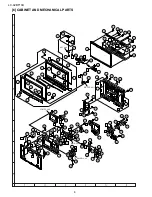
Страница 40: ...3 39 55 48 5 22 42 22 48 55 43 4 5 1 51 16 16 18 17 51 56 51 56 56 5 2 5 2 5 2 50 50 2 56 53 11 19 19 50 50 50 50 49 53 2 1 2 2 50 50 15 50 50 14 56 13 8 51 31 30 37 41 51 51 26 38 57 33 34 51 36 23 51 35 12 10 54 7 9 24 24 52 21 28 51 45 6 27 50 25 32 29 20 46 44 47 40 6 4 6 2 6 3 6 1 56 MAIN Unit TERMINAL Unit POWER Unit KEY Unit R C LED Unit ...

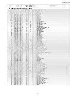
Страница 41: ...Chassis Fix Angle 16 LANGKB071WJFW AK X Lug Angle Top R L x2 17 LANGKB072WJFW AM X Lug Angle Top Center 18 LANGKB189WJFW AC N X RS232C Angle 19 LANGTA401WJFW AT J Center Angle x2 20 LHLDW1141CEZZ AE J Wire Holder for LV 21 LHLDWA150WJKZ AC N J Wire Holder for IF PWB 22 LX HZA003WJFN AC J Screw for SP x2 23 LX NZ3047GEZZ AA J Nut 24 NSFTZ0134CEFW AD J Shaft for DVI x2 for RS232C x2 25 NSFTZA219WJFW...

Страница 42: ...00 AD J Cable Band X4 LHLDWA131WJKZ AE J Cable Clamp X5 QACCDA039WJPZ AQ J AC Cord X6 RRMCGA535WJSA AZ J Remote Control Unit X7 TCADEA208WJZZ AD X Enquete Card X8 TGAN A768WJZZ AD X Guarantee Card X9 TINS D213WJZZ AP N X Operation Manual X10 Not Available AAA Size Battery AC Cord Remote Control Unit Cable Clamp X4 X10 Wire Holder X2 Stand Hole Cover X1 Cable Band X3 X5 X6 X9 Operation Manual AAA S...

Страница 43: ...LC 42BT10U 11 8 PACKING PARTS NOT REPLACEMENT ITEM S3 S4 S4 S4 S4 S6 S5 S1 S2 S7 ...

Страница 44: ...it N QCNW C799WJPZ AG J Connecting Cord Coaxial Cable 100cm N TUNER to TERMINAL Unit N QCNW D483WJQZ AX J Connecting Cord PH 12pin 100cm 12pin N MAIN to POWER Unit N QCNW E068WJQZ AS J Connecting Cord PD 6pin 100cm 6pin N MAIN to POWER Unit N QCNW E134WJQZ BG J Connecting Cord LV 41pin 40cm 41pin N MAIN to LCD CONTROL Unit N QCNW F135WJQZ AS J Connecting Cord LA 6pin 100cm 3pin 3pin N POWER to INV...

Страница 45: ...tored in a retrieval system or transmitted in any form or by any means electronic mechanical photocopying recording or otherwise without prior written permission of the publisher COPYRIGHT XXXX BYSHARP CORPORATION ALL RIGHTS RESERVED MEMO LC 42BT10U ...

Страница 46: ...CORPORATION ALL RIGHTS RESERVED No part of this publication may be reproduced stored in a retrieval system or transmitted in any form or by any means electronic mechanical photocopying recording or otherwise without prior written permission of the publisher LC 42BT10U Jul 2007 Printed in Japan TQ2246 S MI KD ...

Отзывы: