


6
LC-20E1U
LC-20E1UB/UW
OPERATION MANUAL
•
TV/VIDEO
,
CH (
)/(
),
VOL (–)/(+)
, and
MENU
on the main unit have the same functions as the same buttons
on the remote control. Basically, this operation manual provides a description based on operation with the remote
control.
FR
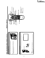
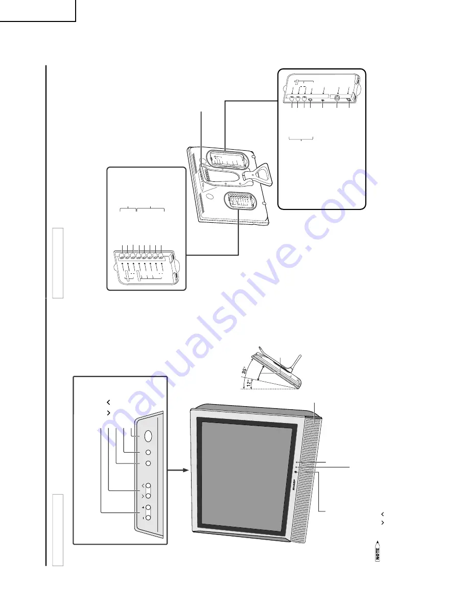
ONT AND REAR CONTR
OL OPTIONS
Main unit (front
view)
CH
VO
L
MENU
MAIN POWER
TV/VIDEO
MAIN POWER
TV/VIDEO
MENU
CH (
)/(
)
VOL (–)/(+)
Speaker
SLEEP indicator
The SLEEP indicator lights up red when
the SLEEP TIMER is set to on.
Upper control panel
Remote sensor window
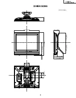
The screen can be
adjusted backwards to an
angle between 12
degrees and 35 degrees.
The screen cannot be set
up straight. When
changing the angle, make
sure to hold the stand and
adjust the screen to the
best viewable angle.
POWER indicator
A green indicator lights when the power is on and a red indicator lights
when in the standby mode (the indicator will not light when the main
power is off).
Adjustable
range
AV
-I
N
1
L
R
A
U
D
IO
S
-VI
D
E
O
A
N
T.
V
ID
E
O
P
O
W
E
R
IN
P
U
T
D
C
1
3
V
HE
A
D
P
H
O
N
E
Y
P
B
CO
M
PO
N
E
N
T
P
R
L
L
R
A
V
-I
N
2
/O
U
T
V
ID
E
O
A
U
D
IO
R
A
U
D
IO
V
ID
E
O
A
U
D
IO
L
Y
P
B
P
R
R
A
U
DI
O
L
R
C
O
M
PO
N
E
N
T
A
V-
IN
2
/O
U
T
A
N
T
.
V
ID
EO
S
-VIDE
O
A
U
D
IO
L
R
H
E
A
D
P
H
O
N
E
P
O
W
E
R
IN
P
U
T
D
C
1
3
V
AV
-IN1
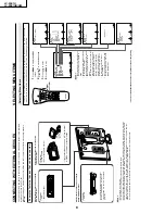
Main unit (rear view)
Antenna terminal
AUDIO (L)
AUDIO (R)
HEADPHONE
POWER INPUT
(DC 13V)
AUDIO (L)
AUDIO (R)
VIDEO
Y
P
R
P
B
AV-IN2/OUT
COMPONENT
AUDIO (L)
AUDIO (R)
VIDEO
S-VIDEO
AV-IN1
Carrying handle
Содержание Aquos LC 20E1U
Страница 32: ...35 34 LC 20E1U LC 20E1UB UW 12 11 10 9 8 7 6 5 4 3 2 1 A B C D E F G H OVERALL WIRING DIAGRAM ...
Страница 34: ...37 6 5 4 3 2 1 A B C D E F G H LC 20E1U LC 20E1UB UW SCHEMATIC DIAGRAM ËR C LED and CONTROL Unit R C LED ...
Страница 35: ...39 38 LC 20E1U LC 20E1UB UW 12 11 10 9 8 7 6 5 4 3 2 1 A B C D E F G H Ë DIGITAL Unit 1 5 ...
Страница 36: ...41 40 LC 20E1U LC 20E1UB UW 12 11 10 9 8 7 6 5 4 3 2 1 A B C D E F G H Ë DIGITAL Unit 2 5 ...
Страница 37: ...43 42 LC 20E1U LC 20E1UB UW 12 11 10 9 8 7 6 5 4 3 2 1 A B C D E F G H Ë DIGITAL Unit 3 5 ...
Страница 38: ...45 44 LC 20E1U LC 20E1UB UW 12 11 10 9 8 7 6 5 4 3 2 1 A B C D E F G H Ë DIGITAL Unit 4 5 ...
Страница 39: ...47 46 LC 20E1U LC 20E1UB UW 12 11 10 9 8 7 6 5 4 3 2 1 A B C D E F G H Ë DIGITAL Unit 5 5 ...
Страница 40: ...49 48 LC 20E1U LC 20E1UB UW 12 11 10 9 8 7 6 5 4 3 2 1 A B C D E F G H Ë ANALOG Unit 1 2 ...
Страница 41: ...51 50 LC 20E1U LC 20E1UB UW 12 11 10 9 8 7 6 5 4 3 2 1 A B C D E F G H Ë ANALOG Unit 2 2 ...
Страница 42: ...52 6 5 4 3 2 1 A B C D E F G H LC 20E1U LC 20E1UB UW Ë INVERTER A Unit ...
Страница 43: ...53 6 5 4 3 2 1 A B C D E F G H LC 20E1U LC 20E1UB UW Ë INVERTER B Unit ...
Страница 44: ...54 6 5 4 3 2 1 A B C D E F G H LC 20E1U LC 20E1UB UW PRINTED WIRING BOARD ASSEMBLIES DIGITAL Unit Side A ...
Страница 46: ...56 6 5 4 3 2 1 A B C D E F G H LC 20E1U LC 20E1UB UW DIGITAL Unit Side B ...
Страница 49: ...59 6 5 4 3 2 1 A B C D E F G H LC 20E1U LC 20E1UB UW ANALOG Unit Side A ...
Страница 51: ...62 6 5 4 3 2 1 A B C D E F G H LC 20E1U LC 20E1UB UW INVERTER A Unit Side A ...
Страница 53: ...64 6 5 4 3 2 1 A B C D E F G H LC 20E1U LC 20E1UB UW INVERTER B Unit Side A ...