


28
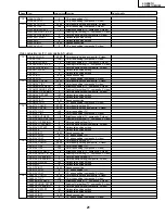
LC-20E1U
LC-20E1UB/UW
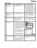
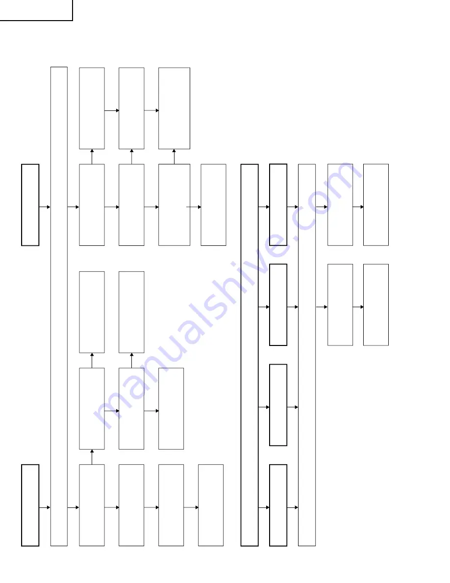
No picture and sound
No color
No TV
color
No S-VIDEO color
Yes
No
Do F3701and F3702
function?
Chec
k all the settings on the microprocessor
’s adjust process men
u
.
No
Are secondar
y outputs
(+38V
, +9V
, +5V
, -8V
, -20V)
of
T3701 as specified?
Yes
Are the oscillation w
a
v
e
fo
rm
at T3701
’s pr
imar
y side as
specified?
Yes
No
Disconnect F3701and
F3702.
Is the load side
shor
t-circuited?
Yes
No
Is an
y of
T3701
’s pr
imar
y
side
, Q3700 and S4701 shor
t-
circuited?
Chec
k J3701, its per
ipher
a
l
par
ts and connection cab
le
.
Replace F3701 and F3702.
Chec
k S4701 and
connection cab
le
.
Chec
k the secondar
y-side
load of
T3701.
Fluorescent lamp
Yes
No
Does F6700, F6701,
F6702, F6703, and
F6704 function?
Yes
No
Is Pin (34) of IC1201 at
“H
”?
Yes
No
Are the oscillation w
a
v
e
fo
rm
s
at the pr
imar
y side of
T6700,
T6702, T6704, T6706,
and
T6708 as specified?
Yes
Replace F6700, F6701,
F6702, F6703, and F6704.
No
Is input at Pin (71) of IC801
as specified?
Chec
k
SC3405, SC line and
per
ipher
al par
ts
.
Yes
Chec
k the line
, IC1201 and
its per
ipher
al par
ts
.
Chec
k Q6700 - 6714,
T6700
- 6709 and their per
ipher
al
par
ts
.
Replace the fluorescent lamp
and chec
k the oscillation
w
a
v
e
fo
rm
again.
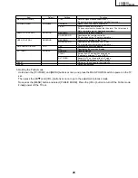
No VIDEO
color
Chec
k all the settings on the microprocessor
’s adjust process men
u.
No COMPONENT color
No
Is input at Pins (4) and (6) of
IC801 as specified?
Chec
k J3404, PB line
, PR line
and per
ipher
al par
ts
.
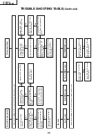
TROUBLE SHOOTING TABLE
(Continued)
Содержание Aquos LC 20E1U
Страница 32: ...35 34 LC 20E1U LC 20E1UB UW 12 11 10 9 8 7 6 5 4 3 2 1 A B C D E F G H OVERALL WIRING DIAGRAM ...
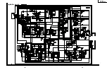
Страница 34: ...37 6 5 4 3 2 1 A B C D E F G H LC 20E1U LC 20E1UB UW SCHEMATIC DIAGRAM ËR C LED and CONTROL Unit R C LED ...
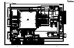
Страница 35: ...39 38 LC 20E1U LC 20E1UB UW 12 11 10 9 8 7 6 5 4 3 2 1 A B C D E F G H Ë DIGITAL Unit 1 5 ...
Страница 36: ...41 40 LC 20E1U LC 20E1UB UW 12 11 10 9 8 7 6 5 4 3 2 1 A B C D E F G H Ë DIGITAL Unit 2 5 ...
Страница 37: ...43 42 LC 20E1U LC 20E1UB UW 12 11 10 9 8 7 6 5 4 3 2 1 A B C D E F G H Ë DIGITAL Unit 3 5 ...
Страница 38: ...45 44 LC 20E1U LC 20E1UB UW 12 11 10 9 8 7 6 5 4 3 2 1 A B C D E F G H Ë DIGITAL Unit 4 5 ...
Страница 39: ...47 46 LC 20E1U LC 20E1UB UW 12 11 10 9 8 7 6 5 4 3 2 1 A B C D E F G H Ë DIGITAL Unit 5 5 ...
Страница 40: ...49 48 LC 20E1U LC 20E1UB UW 12 11 10 9 8 7 6 5 4 3 2 1 A B C D E F G H Ë ANALOG Unit 1 2 ...
Страница 41: ...51 50 LC 20E1U LC 20E1UB UW 12 11 10 9 8 7 6 5 4 3 2 1 A B C D E F G H Ë ANALOG Unit 2 2 ...
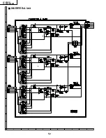
Страница 42: ...52 6 5 4 3 2 1 A B C D E F G H LC 20E1U LC 20E1UB UW Ë INVERTER A Unit ...
Страница 43: ...53 6 5 4 3 2 1 A B C D E F G H LC 20E1U LC 20E1UB UW Ë INVERTER B Unit ...
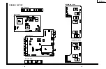
Страница 44: ...54 6 5 4 3 2 1 A B C D E F G H LC 20E1U LC 20E1UB UW PRINTED WIRING BOARD ASSEMBLIES DIGITAL Unit Side A ...
Страница 46: ...56 6 5 4 3 2 1 A B C D E F G H LC 20E1U LC 20E1UB UW DIGITAL Unit Side B ...
Страница 49: ...59 6 5 4 3 2 1 A B C D E F G H LC 20E1U LC 20E1UB UW ANALOG Unit Side A ...
Страница 51: ...62 6 5 4 3 2 1 A B C D E F G H LC 20E1U LC 20E1UB UW INVERTER A Unit Side A ...
Страница 53: ...64 6 5 4 3 2 1 A B C D E F G H LC 20E1U LC 20E1UB UW INVERTER B Unit Side A ...