background image

       BOTTOM GASKET

         GOLD SCREW (1.2cm/0.5")


      GOLD SCREW (2.5cm/1")

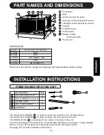
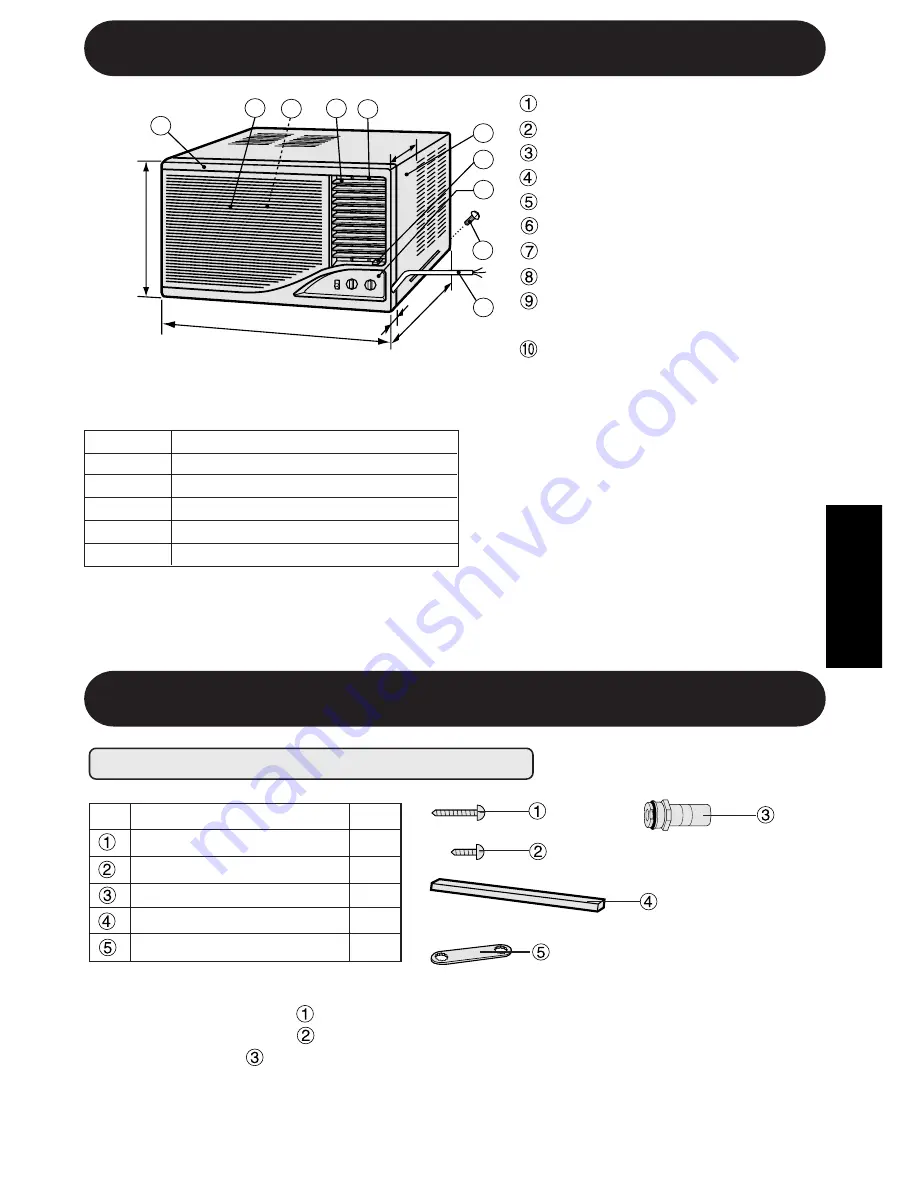
PART NAMES AND DIMENSIONS


 Front panel

  Grille

  Air filter (behind the grille)

  Up/Down air flow adjustment louvers

  Left/Right air flow adjustment louvers

  Cabinet

  Ventilation lever

  Control panel

  Stopper screws

         (on left and right)

  Power cord


294

DIMENSIONS

 A (mm)
 B (mm)

 D (mm)
 E (mm)

 C (mm)

40 (center 51)


729 (center 740)


425


660

MODEL

We reserve the right to change the materials and specifications without notice

.

INSTALLATION INSTRUCTIONS

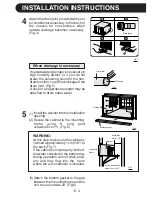
The long GOLD SCREW ( 


   ) is used to secure the cabinet to the mounting frame.

The short GOLD SCREW(     ) is used to secure the front panel to the unit.
The DRAIN JOINT (     ) is attached to the outlet on the back of the unit.
Cut off the blockage of the drain joint, if outside water drainage is necessary  in high humidity
district, or if you do not prefer the splashing sound of the non-drain function.
See page E-3 for detail installation instructions.

ITEMS PACKED WITH THIS UNIT

Q'ty

8

1

1

Accessories

1

E-1

AF-A18CE, AF-A24CE

1

2

3

4

5

6

7

8

9

10

A

B

C

E

D

ENGLISH

        DRAIN JOINT

        WRENCH

1

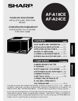
Содержание AF-A18CE

Страница 1: ...OF OPERATION E 7 CLEANING AND MAINTENANCE E 9 BEFORE CALLING FOR SERVlCE E 10 ENGLISH РУКОВОДСТВО ПО УСТАНОВКЕ И ЭКСПЛУАТАЦИИ КОМНАТНЫЙ КОНДИЦИОНЕР СТРАНИЦА СОДЕРЖАНИЕ НАИМЕНОВАНИЕ ЧАСТЕЙ И РАЗМЕРЫ R 1 ИНСТРУКЦИИ ПО УСТАНОВКЕ R 1 ИНСТРУКЦИИ ПО ЭКСПЛУАТАЦИИ R 6 РЕЖИМЫ РАБОТЫ R 7 ОЧИСТКА И УХОД R 9 ПРЕЖДЕ ЧЕМ ОБРАЩАТЬСЯ В СЛУЖБУ СЕРВИСНОГО ОБСЛУЖИВАНИЯ R 10 РУССКИЙ В настоящем РУКОВОДСТВЕ ПО УСТАНОВ...

Страница 2: ......

Страница 3: ...specifications without notice INSTALLATION INSTRUCTIONS The long GOLD SCREW is used to secure the cabinet to the mounting frame The short GOLD SCREW is used to secure the front panel to the unit The DRAIN JOINT is attached to the outlet on the back of the unit Cut off the blockage of the drain joint if outside water drainage is necessary in high humidity district or if you do not prefer the splash...

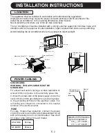
Страница 4: ... 20cm 8 Air inlet Air outlet More than 40cm 16 Air inlet More than 20cm 8 For safe trouble free operation connect the power cord of the unit to a properly rated independent circuit with a time delay fuse or a circuit breaker See chart for proper amp ratings for each model FUSE GROUNDING Neutral blue WARNING THIS APPLIANCE MUST BE GROUNDED Fit a disconnect switch having a contact separation of at l...

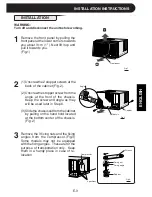
Страница 5: ... of the cabinet Fig 2 Unscrew the stopper screw from the angle at the front of the chassis Keep the screw and angle as they will be used later in Step 6 Slidethechassisoutfromthecabinet by pulling on the hand hold located at the bottom center of the chassis Fig 2 2 3 3 Remove the 3 fixing nuts and the fixing angles from the compressor Fig 3 Some models may not be equipped with the fixing angles Th...

Страница 6: ...ftheblockageofthe drain joint Fig 5 A hose of an appropriate length may be attached to drain outlet water 3 1 5 Install the cabinet into the installation opening Secure the cabinet to the mounting frame using 8 long gold screws 2 5cm 1 Fig 6 Fig 5 Fig 6 WARNING cabinet mounting frame incline backwards about 1cm 3 8 Fig 7 Fig 4 Attach the drain joint provided with your air conditioner accessory to ...

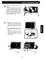
Страница 7: ...on to the chassis Fig 8 Fig 8 Louver link Crank shaft Front panel back view Fig 9 Fig 10 Grille Fig 12 Front panel Replace the front panel Fig 9 Slide the crank shaft into the opening of the louver link at the back of the front panel Fig 10 Remove the grille Fig 11 and the air filter Fig 12 from the front panel Secure the front panel with one short gold screw 1 2cm 0 5 Fig 12 and replace the air f...

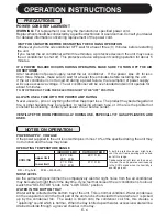
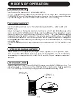
Страница 8: ...ut off This protective device will prevent cooling operation for about 5 minutes POWER SUPPLY VOLTAGE If the power supplied to the unit is not within plus minus 10 of the specified rating the unit may not function and the fuse may blow NOTES ON OPERATION WATER IN THE BOTTOM TRAY Water will be collected at the bottom tray of the unit This is normal condition Water condenses on the evaporator coil i...

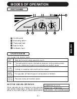
Страница 9: ...ner as shown in the chart at right for efficient performance SELECTOR HIGH COOL VENTILATION LEFT CLOSED position THERMOSTAT 8 9 or 10 SELECTOR KNOB Use to select the desired mode PART NAMES Both the fan and cooling operation are off This setting can be used to circulate air whenever cooling is not desirable The air conditioner will perform fan operation at medium speed Fan operates at medium speed...

Страница 10: ...ool air The louvers will be stopped at the position when the switch is turned off You can also use the switch to adjust the Left Right air flow adjustment louvers to the desired position Never attempt to move the Left Right air flow adjustment louvers manually or manually force the louver movement to stop during swing operation The AUTO SWING switch will not activate the louvers when the SELECTOR ...

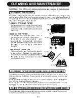
Страница 11: ... detergent and rinse carefully with water Dry the filter with a soft cloth Do not expose the filter to heat or dry it under direct sunlight RE INSTALL THE FILTER Fit the top hooks and then hook the bottom of the air filter Replace the grille Never operate the unit without installing the filter or the grille It may be resulted in serious damage to the unit 2 Air filter Air filter The compressor is ...

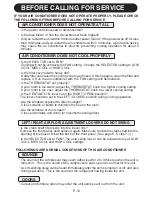
Страница 12: ...THERMOSTAT knob to a lower cooling setting Is the VENTILATION lever set in the RIGHT OPEN position The lever should be set in the LEFT CLOSED position during cooling operation Are the windows exposed to direct sunlight Close curtains or blinds to minimize the heat in the room Are the windows or doors open Close all windows and doors for maximum cooling effect Is the power cord loosened or disconne...

Страница 13: ...SHARP ELECTRONICS CORPORATION SHARP CORPORATION Osaka Japan Printed in Thailand TINSEA329JBRZ 02CO TL 1 ...

Отзывы: