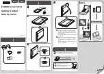
3
Figure 3. Parts and Tools
Figure 4. Accessories
Figure 5. USB A to B Cable
After you have received the two boxes,
immediately check the scanner and the
parts/accessories with reference to Figure 3,
Figure 4, and Figure 5 on the left.
The contents
in the two boxes may vary. We will enclose a
note if there are variations. Contact us if you find
anything missing or damaged.
For discussion convenience throughout this
paper, we name some devices in the following…
9
A: The cross bar
: the black metal cross
that is shown as “A” in Figure 3.
9
B: The 4 wheels
: that is shown as “B” in
Figure 3.
9
C: The 2 ear-knobs and mounting
screws, nuts, and washer
: that is shown
as “C” in Figure 3.
Since the inner rod
is threaded, we currently do not ship the
four nuts shown. See Step 3 below.
9
D: The foot pedal:
that is shown as “D”
in Figure 3.
9
E: The inner rod
: the shinny metal rod
that is shown as “E” in Figure 4.
9
F: The outer rod
: the shinny metal rod
that is shown as “F” in Figure 4. Note:
parts are on it.
9
G: The power supply
: that is shown as
“G” in Figure 4.
9
H The power cable
: that is shown as
“H” in Figure 4.
9
I: The U-shape bracket (or U-bar)
: that
is shown as “I” in Figure 4.
9
J: The A to B USB cable:
that is shown
as “J” in Figure 5.
9
K: The scan software:
that will be
emailed to customers
9
L: The user manuals:
that will be
emailed to customers
To assemble the scanner, you should follow the
following steps.
Содержание USB3D
Страница 8: ......


