


TVC-TRF-10-AAT
25
© SGS electronic 2006-2021
4.6
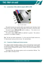
connection of the switch outputs (X08 to X17)
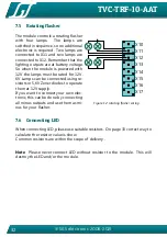
Figure 9: switch outputs
The switch outputs are used for light- and simple motor functions. Each
connector has two outputs (blue and grey) and one common connection (red).
The switch outputs
X08 and X09
switch to b . The common con-
nector is connected to ground.
The switch outputs
X10 to X17
are switched to ground. The common
connector is connected to b.
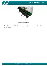
Tip
The left connection (per) is the same for all eight connectors.
To reduce lead count, you can use one + for several loads.
4.6.1
Connection of lighting and exhaust systems
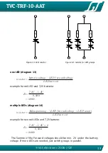
This outputs switch the battery voltage, so the connected load must be able
to stand the voltage. Example: If the model is operated with a 12V battery,
the connected load should be rated for 12Volt. LEDs must be equipped with
suitable resistors.
The heater from the exhaust system can be connected to X04,too. This
output is able to drive up to 5A.


