


MOVIDRIVE
®
PROFIBUS DFP11A
15
The PROFIBUS-DP
Interface
3
3
The PROFIBUS-DP Interface
PROFIBUS-DP (Decentralized Periphery) is the speed-optimized PROFIBUS option designed in par-
ticular for fast data exchange at the sensor/actuator level. DP is used by central automation sys-
tems (e.g. programmable logic controllers) to communicate with decentralized peripherals such as
sensors and actuators, among them drive inverters, via a fast serial link. Data exchange with these
decentralized units is mainly cyclic. The central automation system sends new process output data
to all the peripheral units (slaves) in a message and reads in all process input data from the slaves
(sensors, actuators) in the same message.
To enable the central automation system (DP master) to communicate with the DP slaves, it has to
be given some important information regarding the DP interface of the connected slave. In addition
to data relating to the type and amount of I/O data to be transferred, it also requires additional
information regarding the identity of each DP slave.
3.1
Configuration of the DP Interface
To be able to define the type and amount of I/O data to be transferred, the DP master has to pass a
certain configuration to the drive inverter. The MOVIDRIVE
®
drive inverter can generally be oper-
ated using six different configurations. You have the option of only controlling the drive inverter by
exchanging process data, or, in addition to controlling the drive inverter via process data, of read-
ing or writing parameters using an additional parameter channel at the same time.
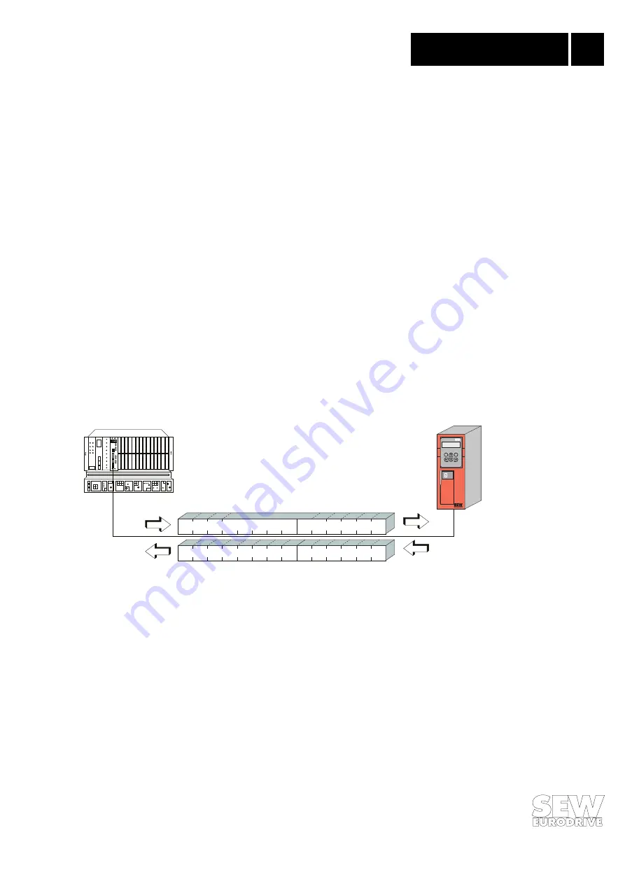
Fig. 10 provides a schematic representation of the exchange of data between the central automa-
tion system (DP master) and the MOVIDRIVE
®
drive inverter (DP slave) using process data and
parameter channels.
01065AEN
Fig. 10: Communication via PROFIBUS-DP
When commissioning the DP master, you will have to specify which configuration is going to be
used to operate the drive inverter. This configuration is then transferred to the drive inverter when
the DP master is started up (using the DDLM_Chk_Cfg service). The drive inverter checks the
transferred configuration data for plausibility before going into data exchange mode. The configu-
ration data are coded in accordance with DIN E 19245 Part 3 /EN 50170 and are discussed in the
next section.
3.1.1 Description of the Configuration Data
DIN E 19245 Part 3 describes the format of the configuration data. Fig. 11 shows the Cfg_Data
identifier byte which, according to DIN E 19245 Part 3, is used to describe which I/O data are to be
transferred between master and slave using PROFIBUS-DP.
In addition to specifying the data length in bits 0-3, you have to use bits 4 and 5 to define whether
the transfer involves input and/or output data. Bit 6 indicates whether the data are to be transferred
in byte or word format and bit 7 is used to specify the consistency with which the data are to be
E
Q
Parameter channel
Parameter channel
Process data channel
Process data channel